Driving CFL ballast circuit
The designer uses the ballast IC in the CFL to heat the filament, illuminate the bulb, and supply current to the lamp. Manufacturers mass produce these ICs, which cost about $2. This design example shows how to drive an LED with a CFL ballast IC instead of driving a CFL. The ballast IC is basically a self-oscillating half bridge for offline operation. It typically operates at 320 VDC and is roughly equivalent to a 230 VAC main rectifier or a 120 V voltage doubler. The IC produces a square wave voltage with an amplitude of 320Vp-p at a frequency of tens of kilohertz.
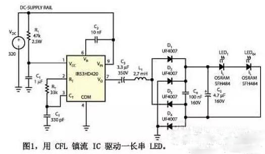
Typically, this square wave voltage is connected to a series connected CFL lamp and current limiting inductor L1 (Figure 1). Adding a shunt capacitor and using an LC resonator heats, illuminates, and supplies current to the lamp. This solution works fine because the CFL tube has high impedance when turned off and low impedance when it is working. The voltage of the lamp is generally 150Vp-p. By connecting several LEDs in series and then connecting them to a bridge rectifier, you can mimic a CFL, at least in a lit state. Imitation of the off state is less important because the LED does not require an ignition process. The rectifier bridge operates at 70 kHz for the given RT and CT values. The circuit provides approximately 80 mA of current for 64 LEDs. In machine vision systems, infrared LEDs are used to illuminate the field of view of a CCD camera. The prototype of this circuit used a 2.7mH inductor removed from a damaged CFL.
The LED current consists of a direct current and a small ripple current; to achieve high efficiency and long life of the LED, keep the ripple current as low as possible. LED manufacturers typically require a few percentage points of value. Such a low ripple current may be difficult to achieve with an electrolytic capacitor C5, such as an additional parallel metal foil capacitor C4 is sufficient to handle the operation in most cases. The voltage at the input of the LED rectifier is substantially stable during an oscillation period, so the inductor current is in the shape of a triangular wave, which is advantageous for EMC (electromagnetic compatibility). The formula for the average LED current is: ILEDAVG=(1/2&TImes; VDC-N&TImes; VFLED)/(4&TImes;f&TImes;L1), where VDC is the supply voltage, N is the number of LEDs in series, and VFLED is the forward voltage of the LED. f is the oscillation frequency, and L1 is the value of the current limiting inductor.
Although the circuit of Figure 1 works well, it also has some drawbacks. The circuit in Figure 2 is supplemented by the addition of C6, D5, D6 and T1. The T1 is wound on an EPCOS EP13 coil former, which uses T38 material. The gapless EP13 frame has an inductance of 7000nH. Both the primary winding and the secondary winding are wound 90 turns with a 0.2 mm wire, and the secondary winding is wound on top of the primary winding. The stray inductance is not important in this case, and the inductance values ​​of the primary winding and the secondary winding are both 50 mH. The circuit of Figure 2 has some advantages over the circuit of Figure 1. For example, the supply current of the ballast IC in Figure 1 must flow through R1 and then into the IR53HD420, where it is clamped at 15.6V. R1 consumes more than 2W at supply currents above 6mA. In Figure 2, R1 can take a higher value because it only provides a small startup current. After startup, a charge pump consisting of C6, D5, and D6 supplies enough current to VCC to clamp the internal Zener diode to 15.6V. The design formula of the charge pump is ISUPPLY (AVG) = f × C62 × VDC - 15.6V. The power consumption of R1 can be stabilized below 0.25W.
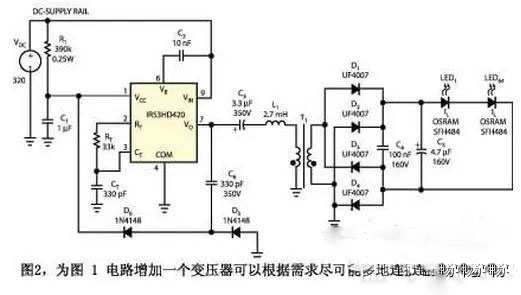
In addition, the total forward voltage of the LED in Figure 1 must be less than half of the supply voltage. For the circuit in Figure 2, by adjusting the transformer winding ratio, as many LEDs as possible can be connected as long as the component's rating is not exceeded (the LED voltage can even be higher than VDC). The circuit of Figure 1 has a less obvious problem, that is, the full voltage swing of the rectifier bridge appears at both ends of the LED string. This situation does not cause problems when all LEDs are close to the rectifier bridge. However, in many lighting devices, it is desirable to separate the LED from the electronic device. Due to the presence of stray capacitance, this approach can result in high capacitive currents from LED to ground, affecting efficiency and creating EMC problems. Using the transformer of Figure 2, either end of the LED string can be grounded directly or through a capacitor. Now, you can use a long cable to easily separate the LED from the electronics.
Solar Street Lights are raised light sources which are controlled by solar powered boards commonly mounted on the lighting structure or coordinated into the shaft itself. The sunlight based boards charge a battery-powered battery, which controls a fluorescent or LED light during the night. There are two types of solar light generally in the lighting market which called all in on solar street light and split solar street light.
Features of solar street lights: A modern solar street light has embedded solar panel, inbuilt lithium-ion batteries, battery management system, night and motion sensors as well as automatic controls. The fully automatic device comes with LEDs, inbuilt and replaceable Lithium-ion battery and passive infrared (PIR) sensors. A typical solar street light is weather-proof and water-resistant, has low insect attraction rate and low glare and has a longer life.
Advantages of solar street light:
Environmental protection: solar energy is green, clean and renewable energy. And the widely using of the solar lights can low down the emmision of the carbon dioside.
Cost less to save money: Since the solar lights can be 100% energy, zero electric bill will be paid after the customers install the solar lights. And customers can also save the cost in wire trench.
More easy installation: Does not like electric lights, there is no need wire trench for solar light installation. Everyone can install the solar lights in a very shorten time.
more safe: Solar lights is DC low voltage compared to dangerous 110-220V AC electric power, it does not harm to human.
Solar Street Lights
Solar Street Lights,Solar Walkway Lights,Solar Powered Security Lights,Solar Street Light With Battery
Jiangmen Biaosheng Solar Energy Technology Co., Ltd. , https://www.bsprosolar.com