IGBTs are often used in various types of high-power power supplies, and their quality is related to the performance of the circuit. This article will introduce some of the problems that will be encountered in the application of IGBT, as well as solutions.
Use an effective overcurrent protection driver circuit
In IGBT applications, the key is overcurrent protection. The overcurrent time that the IGBT can withstand is only a few microseconds, which is much smaller than that of devices such as scr and gtr (tens of microseconds), so the requirement for overcurrent protection is even higher. The overcurrent protection of IGBT can be divided into two types, one is low current (1.2~1.5 times) overload current protection;
The other is high-multiplier (8 to 10 times) short-circuit current protection. For overload protection, protection can be achieved by instantaneously blocking the gate pulse. For the short-circuit current protection, adding the instantaneous blocking gate pulse will be too large due to the di/dt of the short-circuit current drop, and it is easy to induce a high collector voltage across the loop stray inductance to pass through the IGBT, so that the protection fails.
Therefore, for IGBTs, reliable short-circuit current protection should have the following characteristics:
(1) First, the gate voltage should be softly lowered to limit the peak value of the short-circuit current, prolong the allowable short-circuit time, and win the time for the protection action;
(2) Protection to cut off the short-circuit current should be implemented with soft shutdown
The IGBT drivers exb841, m57962 and hl402b meet the above requirements. However, these drivers cannot completely block the pulse. If no measures are taken, the soft-off protection of each cycle will be caused once the fault does not disappear. The heat accumulation thus generated will still cause damage to the IGBT. To this end, the fault detection output of the driver can be used to completely block the gate pulse through the optocoupler, or reduce the operating frequency to below 1hz, and automatically return to the normal operating frequency when the fault disappears.
As shown in Figure 1, the IGBT drive module m57962l has its own protection function. When the detection circuit detects that the detection input pin 1 is 15v high level, it determines that it is a current fault, immediately starts the gate shutdown circuit, and sets the output terminal 5 pin. Low level, the IGBT is turned off, and the output error signal makes the fault output terminal 8 low level to drive the external protection circuit to work, delaying 8~10μs to block the driving signal, which can achieve overcurrent protection well. After a delay of 1~2ms, if the input is detected as high level, m57962l is reset to the initial state.
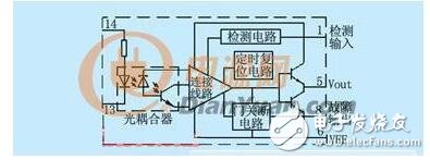
figure 1
Non-inductive line
From the previous analysis, it can be seen that the dvce/dt of the turn-off process can also be reduced by reducing the value of the stray inductance lб relative to the same di/dt. For the IGBT device with high power, the parasitic inductance of the line is large. Two wide and thin busbars can be used, and a layer of insulating material is sandwiched between them to form a low-sensitivity busbar. A special manufacturer also supports the device. Make a non-sensitive busbar. The sense that the non-inductive bus reduces the voltage overshoot is not only to avoid overcurrent or short circuit, but also to reduce the burden on the absorbing circuit, simplify the structure of the absorbing circuit, reduce the power consumption of the absorbing resistor, and reduce the volume of the inverter. This is also a very interesting issue.
Active cooling
During the turn-on process, the IGBT is operated as a MOSFET most of the time, except that in the later stage of the collector voltage vce falling process, the pnp transistor is increased from the amplification region to the saturation region by a delay period, so that the vce waveform is divided into two segments. During the turn-off of the IGBT, after the MOSFET is turned off, the stored charge in the pnp transistor is difficult to be quickly eliminated, causing the collector current waveform to become two segments, resulting in a large tail current of the collector current. Obviously, the delay of turn-on and turn-off time will increase the switching loss, and the loss will be accumulated every time the turn-off is turned off. If the switching frequency is high, the loss will be large. In addition to reducing the efficiency of the inverter, the loss is the most The direct effect is the temperature rise, which not only increases the risk of the IGBT holding effect, but also increases the collector current fall time and the rise time of the collector voltage, causing an increase in turn-off loss. Obviously, this is a vicious circle. Therefore, providing good heat dissipation conditions for IGBTs is the main measure for effectively utilizing devices and reducing losses. In addition to properly installing the heat sink, installing a fan to enhance air circulation can effectively improve heat dissipation efficiency.
Category 8, or just Cat8, is the latest standard in copper Ethernet Cable. It represents a significant leap in data transfer speed over the earlier Cat7 and Cat6a network cables. It uses standard RJ45 connectors and is backwards compatible with previous standards.
Cat8 is the fastest Ethernet cable yet. It's data transfer speed of up to 40 Gbps is four times faster than Cat6a, while its support of bandwidth up to 2 GHz (four times more than standard Cat6a bandwidth) reduces latency for superior signal quality.

Cat 8 Cable,Cat8 Ethernet Cable,Cat8 Indoor Ethernet Cable,High Speed Cat8 Cable
Shenzhen Kingwire Electronics Co., Ltd. , https://www.kingwires.com