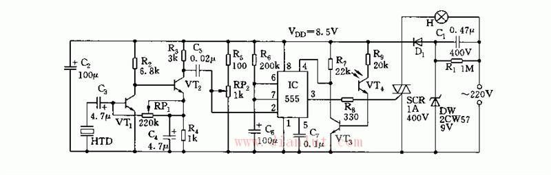
A sound and light dual-control power saving lamp may be formed by using a time base circuit and a few peripheral components. During the day, due to the light, the light is always off. As soon as the light is received, the light will automatically light up, and then the light will automatically turn off after a delay. The purpose of saving electricity. The device eliminates the power transformer with large energy consumption, heavy weight and high heat generation, and has the characteristics of simple structure, slight self-consumption, stable performance, high sensitivity and strong versatility. The circuit diagram of the sound and light energy saving lamp is shown. The piezoelectric ceramic piece has extremely sensitive characteristics to the sound of the sound. This circuit uses it as a sound and electricity transducing element. The circuit consists of voltage part, acoustic and electrical conversion and amplification part, single The steady-state delay portion and the light control portion are composed.
SUNLUX IOT Technology (Guangdong) INC. , https://www.sunluxbarcodereader.com