Abstract: The design and implementation of a class of learning remote control are proposed. The working principle, hardware and software are briefly introduced, and the realization process of software infrared remote control coding learning is detailed. The infrared remote control adopts the principle of measuring pulse width, replicates its infrared pulse signal for self-learning, realizes 38 kHz carrier in software form, and finally successfully learns other remote controllers. The device can control home appliances instead of a variety of different remote controls.
Key words: infrared remote control; self-learning; software carrier; infrared pulse signal
This article refers to the address: http://
0 Introduction Infrared remote control is currently the most widely used communication and remote control method. Because of its simple structure, small size, low power consumption, strong function and low cost, it is widely used in color TV, air conditioner, CD/VCD. , video recorders, household appliances and their industrial control. With the increasing demand for home appliances in people's lives, the use of infrared remote controls is becoming more frequent. Due to the different encoding formats of various infrared remote controllers, various infrared remote controllers are not compatible. It is often necessary to replace the remote control, which also brings inconvenience to people's lives.
At present, most of the domestic learning remote controllers use the infrared waveform of the remote control to achieve the learning purpose, and the method is simple and convenient to implement. However, the use of a dedicated remote control integrated chip results in a complicated design and high cost, and the infrared signal formation of the remote controller is generated by using an infrared remote control transmitting chip, which has high integration but is expensive.
This is a learning infrared remote control based on AT89S52. By measuring the output signal of the infrared integrated receiver, the output pulse width is recorded as it is, then saved in the E2PROM, and finally generated by the single-chip timer interrupt. The kHz carrier signal replaces the hardware with software, saving resources. The learning infrared remote control can successfully learn the encoding of various infrared remote control devices and transmit the learned memory signals through a 38 kHz carrier. Achieved learning of a variety of infrared remote control, which turned into a true self-learning remote control.
l Learning infrared remote control system
1.1 Principle of learning infrared remote control From the general principle of home universal learning infrared remote control, it can be divided into two categories: fixed code learning remote control and waveform copy learning remote control. The former, mainly through the collection of various types of remote control signals, and then divide and conquer. The learning type remote controller has relatively simple hardware requirements, the controller has a low operating frequency and a large storage capacity, and its disadvantage is that it is invalid for an unknown remote controller. The latter is mainly to completely copy the signal sent by the original remote controller, regardless of the format of the remote controller. After proper compression, it is stored in the ROM memory. When transmitting, it only needs to read out the memory. The remote control code is restored to the original signal and the learning function is completed. The learning type remote controller has high frequency requirements for the MCU and large RAM requirements, and the advantage is that it can be learned for any kind of infrared remote controller. The following is mainly designed in the second way.
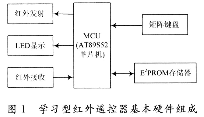
1.2 Learning infrared remote control basic hardware components Learning infrared remote control consists of single-chip microcomputer, infrared transmitting circuit, infrared integrated receiving head, E2PROM storage circuit, matrix keyboard and LED indicator, as shown in Figure 1. The AT89S52 single-chip microcomputer constitutes the infrared remote control processor, and its data memory RAM (258 B) is used to store the pulse width of the encoded signal during the learning process; the infrared transmitting circuit: the 38 kHz square wave is modulated by the remote control pulse signal, and the infrared is driven after the triode is amplified. Light-emitting diodes, where the 38 kHz carrier is generated by the AT89S52 timer TO. Infrared integrated receiver: The signal output from the infrared receiver is detected, shaped, amplified, and demodulated by a 38 kHz carrier signal. The output signal is TTL high and low. External E2PROM memory: Stores the pulse width value of the learned high and low level signals.
1.3 System Software Design The design performance and implementation of the learning remote control has a close relationship with its software design. In particular, the acquisition period of the code width count and the number of bits used by the counter are related to whether the remote control code can be accurately acquired. The sampling period of the code width count is determined by multiple experimental tests during programming. The design read code sampling period is approximately 12 μs. The counter for reading the remote control code uses a 16-bit counter with a sampling time between 0 and 786.432 ms. The value is stored in the set data memory and then written to the external E2PROM memory. The transmission process is then read from the external E2PROM memory and the encoded signal is transmitted over the 38 kHz carrier.
2 Infrared remote control coding learning and software carrier transmission
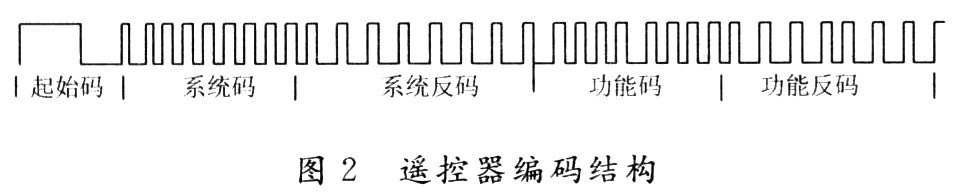
2.1 Infrared remote control signal coding structure analysis The remote control code pulse transmitted by the infrared remote control is composed of the start code, system code, function code and function code, as shown in Figure 2. The start code is the beginning of one remote control code and consists of one high level and one low level as a preparation pulse for receiving data. These codes are transmitted after being modulated by a 38 kHz carrier pulse.
By analyzing a large number of different types of infrared remote control code waveforms, the data frame intermittent width of the remote control code is more than 10 ms, and the high level of the start code is more than 5 ms, usually about 9 ms. The coding bit is between 10μs and 5ms. In the design, only the high and low widths of the signal transmitted by the remote controller are considered, and the coding method is not considered to simplify the design.
2.2 Infrared remote control signal coding learning software design The infrared signal of the general infrared remote control is formed by carrier modulation of 38~40kHz (cycle is about 26.3μs). After the carrier, the pulse width of the signal and the instruction of the single chip microcomputer The cycle time (12 μs crystal oscillator command cycle is 1 μs) is about the same order of magnitude. If the pulse width of the carrier signal is directly recorded, such a large error, the carrier signal must be demodulated before the pulse width of the remote control coded signal can be recorded.
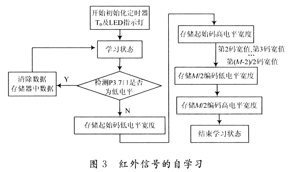
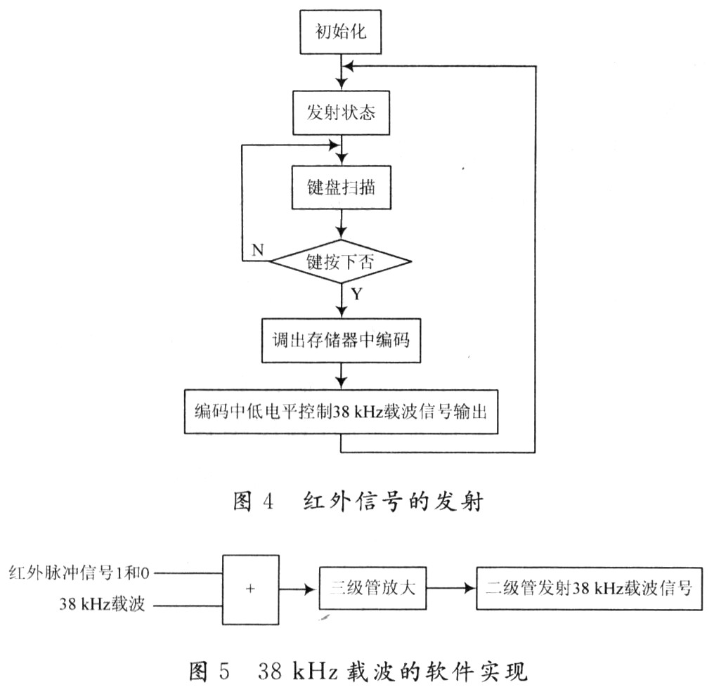
In the design, the counter uses the method of timing the signal high and low to collect data and save it. When the system recognizes the low level of the start code, the system starts designing the acquisition signal to collect the low level, and the counter starts counting. When the low level of the start code ends, the value of the counter at this time is saved, and the record is recorded. The low level signal pulse width value of the start code. Then, the collected pulse width value of the encoded signal is sequentially saved. If the number of acquired encoded signals is greater than the set value M (set value in the program), it is considered that the code acquisition has ended, and the learning subroutine ends, as shown in FIG. 3:
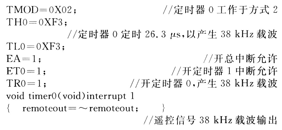
2.3 Infrared remote control signal transmission The software realizes the carrier synthesis of the remote control signal, generates the 38 kHz carrier signal with the timer interrupt 0, and controls the carrier output with the low level of the learned remote control code signal. At this time, the timer O The timing length is determined by the corresponding low-level width of the remote control signal, that is, if the remote control signal to be transmitted is high, the off timer is interrupted by O; if it is low, the open timing is interrupted by 0. The 38 kHz carrier signal is output to the infrared emission control pin (P3.7) to implement pulse width modulated transmission of the remote control signal. Regardless of the encoding method of the infrared signal, only the method of collecting the high and low levels is shown, as shown in FIG. Instead of using the 38 kHz carrier circuit for transmission, the carrier is generated by the timer TO of the microcontroller. The program code is as follows:
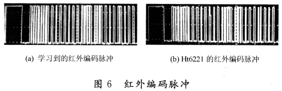
3 Conclusion In this design, the infrared remote control can accurately collect the infrared coded pulse signal, and save and send the original infrared coded signal. It can successfully learn various home infrared remote controllers and control various home infrared remote controllers. It solves the troubles of many remote controllers for home users.
Bicycle Light,High Power Bike Light,High Brightness Bike Light
Brilliant Electronic Systems Technology Co., Ltd. , http://www.yichen-flashlight.com