Cold cathode fluorescent lamps are widely used in LCD backlighting, office equipment (such as copiers, scanners, etc.) and rolling advertising light boxes. Although backlighting in small-size color screens of portable electronic products such as telephones, mobile phones, PDAs, and digital video cameras has long been dominated by LEDs, in the backlighting of large-size LCDs such as notebook computers, LCD color TVs, and LCD monitors, CCFLs Leading the way. Although in the large-size LCD backlight application, CCFL will encounter LED competition, but recently the price of LED is high, and dozens or even hundreds of LEDs are used together as backlights. A technical threshold for admission. Therefore, the dominance of the CCFL will not be replaced by LEDs in the next few years.
CCFL structure and its main features
1. Structure and working principle of CCFL
CCFL is similar to neon light, cathode is cold cathode, pipe diameter is very thin (only about 2~8mm), and the principle of illumination is basically the same as that of fluorescent lamp. 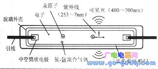
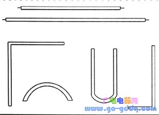
The structure of the CCFL is shown in the figure above. The CCFL glass tube is filled with mercury and an inert gas (a mixture of helium and argon), and the inner wall is coated with a phosphor of three primary colors (RGB). The CCFL cathode has a hollow cylindrical shape and is made of a metal material such as nickel or molybdenum, and the inner wall of the cylinder is coated with a luminescent material. The CCFL can be made into different shapes as needed, as shown below. When a high voltage is applied to both ends of the CCFL, the gas in the tube is ionized to emit ultraviolet light having a wavelength of 253.7 nm, which is absorbed by the phosphor on the inner wall of the tube, converted into visible light (wavelength of 400 to 7OOnm), and then radiated.
2, the main characteristics of CCFL
Since the CCFL has a very small diameter and a short length (a dozen to several tens of centimeters), the operating current is small, usually 3 to 8 mA. However, the operating voltage of the CCFL is relatively high, reaching 250~6OOV (effective value), which is several times or even nearly 10 times of the operating voltage of the fluorescent lamp. The trigger starting voltage of the CCFL is at least 1.5 times its operating voltage, usually 600~l500V{effective value).
CCFL has the advantages of stable electrical and optical properties, long life (up to 15~2Okh), vibration resistance, impact resistance (greater than 1O0g), and strong resistance to dot killing (up to 100,000 times). However, since the LCD panel is large, more CCFL lamps are required, and the number of inverters driving the lamps is also large, and the cost share in the whole machine is large. Since the CCFL contains mercury, it is not environmentally friendly and does not comply with the EU RoHS Directive on Restriction of Hazardous Substances and the Weee Directive on Waste Electrical and Electronic Equipment, and LEDs do not have this problem.
CCFL electronic drive circuit and its controller IC
CCFL electronic drives are also known as CCFL electronic transformers or electronic ballasts. Whether it is AC mains supply (such as 220V/50Hz) or low-voltage DC supply (range 3~3OV (CCFL drive circuit, its core is a DC/AC high-frequency inverter {output frequency is 20~1OOkHz). To meet the CCFL startup and operating voltage requirements, the CCFL inverter output is connected to a high-frequency step-up transformer, and the boost ratio is often 60~100. When the CCFL is used as an LCD backlight source, its drive circuit must have analog, especially digitally controlled dimming. Function. CCFL drive circuit uses controller IC. According to CCFL controller, CCFL drive circuit is divided into three types: half bridge, full bridge and push pull, and the latter two are mainly.
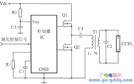
1. Half-bridge drive circuit At present, CCFL half-bridge controller ICs only have several types such as MAX8729, UCC3976 and UBA2070. The half-bridge topology requires two power switches (mostly MOSFETs) for higher circuit efficiency. Philips Semiconductors' UBA2070 is suitable for AC power supply up to 277V. The CCFL half-bridge driver circuit is shown above. In the figure, Q1 and Q2 are half-bridge switches; RT and CT are used to set the switching frequency: T1 is the step-up transformer, and the T1 boost ratio (ie, the turns ratio between the secondary and primary windings) is N; C1 is the separation. DC capacitor, C2 is T1 secondary shunt capacitor. The resonant tank equivalent circuit of the circuit shown above is shown in the figure below. Among them, the T1 secondary winding leakage inductance, C1 is the series capacitance reflected to the secondary, RL is the equivalent resistance of the CCFL lamp, and the square wave AC signal source represents the half bridge power level.
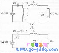
According to the equivalent circuit shown in the above figure, the generation of the CCFL trigger start voltage can be understood. Before the CCFL is not triggered, its resistance is infinite, the resonant tank is parallel topology, and the resonant frequency FP is determined by L, C1 and C2. ![]() The inverter acts like a voltage source, generating a high voltage of about 1000V across the lamp during resonance to ionize the lamp and conduct it. Once the lamp is illuminated, the CCFL resistance value drops sharply and the inverter operates close to the series resonant mode, like a current source. The circuit series resonant frequency fs is determined by L and C1
The inverter acts like a voltage source, generating a high voltage of about 1000V across the lamp during resonance to ionize the lamp and conduct it. Once the lamp is illuminated, the CCFL resistance value drops sharply and the inverter operates close to the series resonant mode, like a current source. The circuit series resonant frequency fs is determined by L and C1 ![]()
2, full bridge drive circuit
CCFL full-bridge driver ICs are mostly one channel. Representative products include Maxim's MAX8709 (QFN28 package), MAX8722A (QSOP24 package), MAX8751 (QPN32 package), MAX8759 (QFN32 package), and Fairchild's FAN7310 (SSOP20 package). Wait. These control ICs feature analog and digital PWM (DPWM) dimming and protection against open and short circuits.
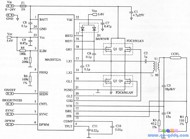
The CCFL full-bridge driver circuit requires four power switches, and the output power is twice as large as the half-bridge. The figure above shows the CCFL full-bridge driver circuit using the MAX8722A. The circuit works almost identically to the half-bridge circuit. The transformer T1 turns ratio is 1:93, the CCFL lamp current is 6mA, the trigger voltage is l600V, and the operating voltage is 650V. The circuit DC input voltage Vin is 8~24V, and the DPWM frequency fdpwm is 209Hz (set by the resistor R6 on the pin FREQ). When an O~2V dimming control voltage is applied to IC pin 5 (CNTL), the brightness of the lamp can be adjusted, and the dimming range is 10%~100%. The MAX8722A also implements digital dimming using the DPWM method. The MAX8722A provides T1 secondary overcurrent protection, secondary voltage limiting, lamp open protection, and primary overcurrent protection. R1 is used as the sense lamp current, capacitive divider C3/C4 is used to detect the T1 secondary voltage, and R3 is used to sense the T1 secondary current.
In fact, the circuit shown above can drive two CCFL lamps through two primary parallel transformers. In some applications, the transformer secondary can also be connected in parallel with two CCFL lamps.
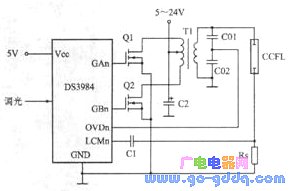
3. Push-pull drive circuit CCFL push-pull drive circuit requires two power switches. The circuit of the transformer primary with center tap is shown in the figure above. Among them, CO1 and CO2 constitute a capacitive voltage divider for sensing T1 secondary overvoltage and R5 is used for sensing lamp current. The DS3984 has four channels, each of which can drive four CCFL lamps through a transformer primary parallel.
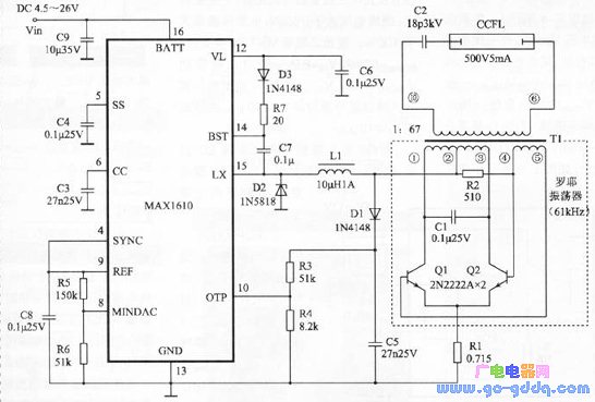
The figure above shows a push-pull resonant CCFL driver circuit using the MAX1610. Among them, T1 (primary), C1, Q1 and Q2 constitute an oscillating circuit, and the oscillating frequency is determined by the inductance of the primary winding of the cavity capacitors C1 and T1 (LP=44μH) and the inductance of the secondary reflection of T1 to the primary. The first and second winding turns ratio of T1 is 1:67, the T1 secondary circuit is; the power supply structure (CCFL has no ground). The MAXl610 is available in a 16-pin SO package and requires an internal 5-bit up/down counter to perform CCFL dimming. R1 is used to detect the oscillator current, and D1, R3 and R4 form an open-circuit detection circuit.
CCFL push-pull drive circuit controllers are many varieties, and several representative ICs are shown in the following table.
| model | Package | Number of channels | production company |
| MAX1610, MAX1611 | SO16 | 1 | |
| DS3881 | SSOP24 | 1 | |
| DS3882 | SSOP28 | 2 | Maxim (MAXIM) |
| DS3984 | TQFP32, SO28 | 4 | |
| DS3988 | TQFP48 | 8 | |
| UC1871/UC2871/UC3871 | DIL18, SOIC18, PLCC18 | 1 | |
| UC1872/UC2872/UC3872 | DIL14, SOIC16, SSOP16, PLCC20 | 1 | Texas Instruments (T1) |
| UCC1972/UCC1972/UCC3972 | TSSOP18, SOIC8 | 1 | |
| UCC3977 | TSSOP8 | 1 | |
| LT1182, T1183, LT1184, T1184F | SO16 | 1 | Linear Technology (LT) |
| FAN7548 | SSOP20 | 2 | Fairchild |
| TK7504V | TSSOP16 | 1 | TOKO |
Capacitor for Electric Furnace
Capacitor For Electric Furnace, commonly referred to as capacitors, are capacitors, expressed in the letter C.Definition 1: a capacitor, as the name implies, is a "charging vessel", a device that holds charge.Capacitor.Capacitors are one of the most widely used electronic components in electronic equipment. They are widely used in the fields of interleaving, coupling, bypass, filtering, tuning circuit, energy conversion and control.Definition 2: a capacitor consisting of any two conductors (including wires) that are insulated from each other and are very close together.
Electronic Components Capacitors,High Voltage Capacitors,Low Frequency Capacitor,Water Pump Capacitor,Capacitor for Electric Furnace
YANGZHOU POSITIONING TECH CO., LTD. , https://www.cnfudatech.com