Introduction: This chapter introduces the hardware connection usage of some basic modules of the versatile 51 experiment box. 1) Browse the hardware test instructions 2) Prepare related accessories 3) Connect the hardware according to the test instructions 4) Download the test program 5) Observe the experimental phenomenon 6) Confirm whether the function module is normal. If there is no special explanation, the hardware environment of the hardware function test is: Chang Xue series multi-function development learning board / experiment box (2017 version) 51 main chip STC12C5A60S2 ï® 11.0592M crystal oscillator
PCF8591AD/DA module test
Hardware preparation: 2P DuPont line, 3 jumper caps, 11.0592 mega crystal oscillator
Software preparation: CEPARK PCF8591 host computer program 8.exe (Please close the running serial port before using this software)
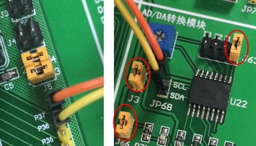
Wiring instructions: Use a 2P DuPont line to connect the P3 port of the MCU to the bottom plate JP68. The specific connection method is P37-SCL and P36-SDA.
Jumper Description: Short-circuit the bottom plate J3, J66, J63

Specific connection: P37-SCL, P36-SDA. Short circuit board J3, J66, J63
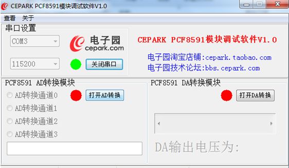
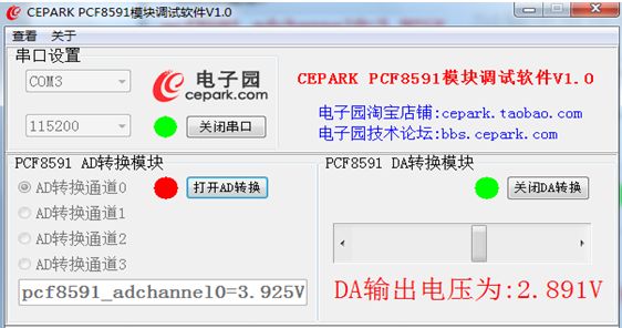
Experimental phenomenon: Open the PC software, open the serial port, and the serial port number is viewed from the device manager. The baud rate is set to 115200.
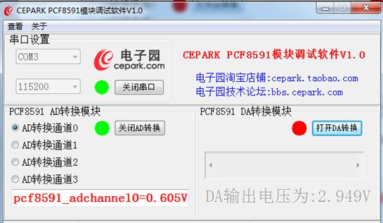
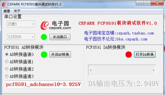
When AD conversion is turned on, the upper computer selects a conversion channel, jumps the jumper on the corresponding J63, adjusts the adjustable resistance, and the upper computer displays the corresponding value after conversion.
Turn on the DA conversion, adjust the slider when the DA conversion test, and change the input digital quantity. The brightness of the LEDs on the module changes accordingly.

Ceramic Housing
Ceramic Housing
YANGZHOU POSITIONING TECH CO., LTD. , https://www.cndingweitech.com