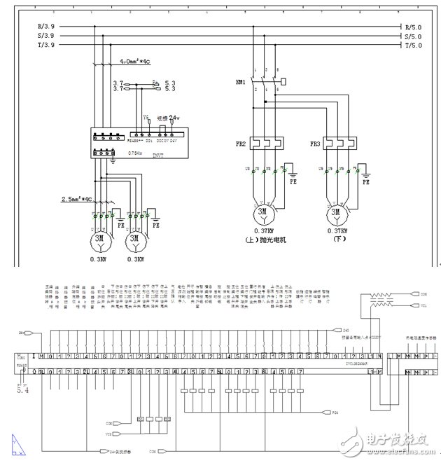
According to the technical requirements of woodworking edge banding machines, INVT adopts a fully integrated solution of man-machine interface, PLC control system and frequency converter. Please refer to Figure 1 for a schematic diagram of the specific solution.
The standard modbus protocol is adopted between the PLC control system and the man-machine interface, and the control system and the inverter mainly adopt a multi-speed control method. At the same time, the INVT PLC unique N:N communication is used to read the necessary inverter status information .
In addition, based on the experience of INVT engineers, some suggestions are made on the existing electrical installation, hoping to provide some help to the stability of the equipment.
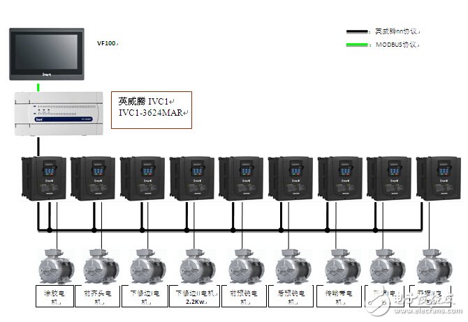
Figure 1: Schematic diagram of edge banding machine system
2. System description1. Control System
The man-machine interface adopts the INVT VF series touch screen. The 10-inch color product is cost-effective and has good man-machine interaction functions.
The PLC control system adopts the INVT controller IVC1 series, which has a very high cost performance, and it forms a perfect small automation product solution with VF and INVT inverters.
â’‰ Each station of the existing edge banding machine relies on the signal of the travel switch to delay action, which is not only inconvenient in installation and debugging, but also in the final customer site environment, such as voltage fluctuations, mechanical running-in, etc., may cause the speed of the conveyor belt to fluctuate. The motion of the station will be affected to some extent. In theory, there is a certain error range for each motion. Therefore, the general edge banding machine also has three speeds for high and midsole, so the touch screen should also correspond to the delay parameters of three different speeds. .
Now adopt INVT’s solution: add an encoder and reduce the original seven limit switches. Use the encoder to control the absolute position. In this way, not only the control is more accurate, but also the installation and debugging time is saved, and the failure rate of the machine is reduced.
3. Suggestions on electrical installation
According to the experience of INVT engineers, in view of the current electrical installation situation, the following three improvement suggestions are specially put forward, hoping to provide assistance to the stability of the equipment.
1. There is no good connection between multiple mounting boards
Usually when two devices have signal connections with each other and each is grounded at different locations, if there is a ground potential difference between the two grounding points, ground loop interference will occur. That is, common mode interference. As shown in Figure 2:
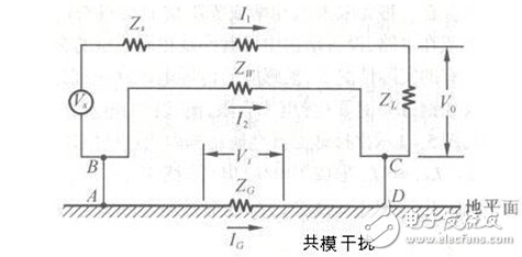
Figure 2: Schematic diagram of common mode interference
In order to avoid this interference, you can connect the ground in parallel in the cabinet. The cabinet is grounded at one point through the bus bar, and each device is connected to the grounding point in the cabinet through an independent, short and thick enough ground wire.
It is recommended to use short and thick cables to connect the mounting plate to the grounding point.
2. The wiring path can be optimized, try to avoid parallel routing of the signal line and the motor power line
The analog signal line and the power line are routed in a trunking, which will produce spike interference signals on the analog signal line.
In order to avoid this situation, the following principles should be followed:
(1) Cables of different voltage levels (24V, 110/220V and 400V) should be routed separately;
(2) The analog signal line should be routed independently;
(3) The distance between signal wires, communication wires, etc., and control wires of electronic control components, and power wires should be less than 20CM. If not, it should be separated by a metal plate.
3. The contactor control coil can consider adding resistance and capacitance components to prevent surges
The electronically controllable switch will generate a large number of spike interference signals when it is in action, and its peak value may reach 4000V, as shown in Figure 3:
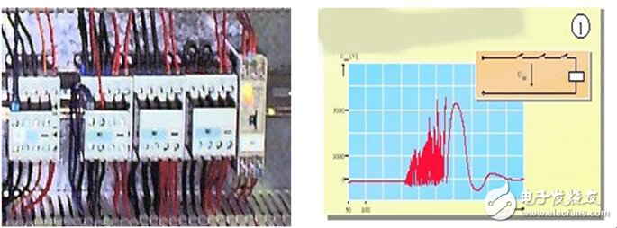
Figure 3: Example of spike interference signal
These spike voltages can be absorbed by various surge absorbing devices, such as RC loops or Zener diodes, etc., so as to avoid the interference of such spikes. As shown in Figure 4.
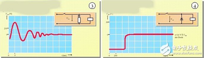
Figure 4: Example of surge protection with RC components
The above three points are suggestions made by INVT engineers based on field experience, hoping to improve the stability of existing electrical installations.
Wiring diagram:
The main pain points in obtaining customers in foreign trade are fierce market competition, high customer acquisition costs, low customer stickiness, and single marketing methods. With the changes in the market environment, traditional marketing methods
Orange sample
Bossgoo(China)Tecgnology , https://www.cn-gangdao.com