A low-voltage electrical appliance is a component or device that can manually or automatically turn the circuit on or off according to external signals and requirements to switch, control, protect, detect, change and adjust the circuit or non-electrical object. According to the working voltage of the control electric appliance, it can be divided into two categories: high-voltage control electric appliance and low-voltage control electric appliance, with the boundary of AC 1200V and DC 1500V. In general, low-voltage electrical appliances can be divided into two major categories of distribution electrical appliances and control electrical appliances, and are the basic components of complete electrical equipment. In the industrial, agricultural, transportation, defense, and people's electricity sectors, most use low-voltage power supply, so the quality of electrical components will directly affect the reliability of low-voltage power supply systems.
China's current standards refer to electrical equipment in electrical circuits with operating voltage AC 1000V and DC 1200 V below. There are many types of low-voltage electrical appliances. According to their structural uses and controlled objects, there are different classification methods. The following three classification methods are introduced:
1. According to different purposes and control objects, low-voltage electrical appliances can be divided into power distribution appliances and control appliances.
(1) Distribution electrical appliances for low-voltage power networks
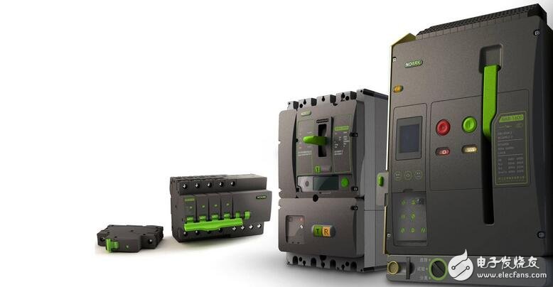
Such appliances include knife switches, transfer switches, air circuit breakers and fuses. The main technical requirements for power distribution appliances are strong current interruption capability, and the current limiting effect is accurate and reliable in the event of system failure; there is sufficient thermal stability and dynamic stability.
(2) Control appliances for electric drag and automatic control systems
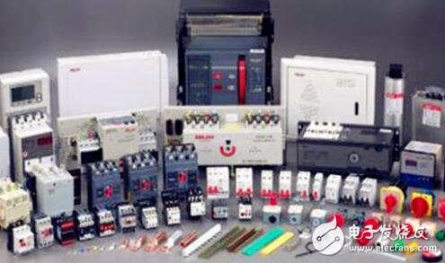
Such appliances include contactors, starters, and various control relays. The main technical requirements for controlling electrical appliances are high operating frequency, long life and corresponding conversion capability.
2. According to different operation modes, low-voltage electrical appliances can be divided into automatic electrical appliances and manual electrical appliances.
(1) Automatic appliances
An electric appliance that performs operations such as turning on, breaking, starting, reversing, and stopping by electromagnetic (or compressed air) is called an automatic electric appliance. Commonly used automatic appliances include contactors, relays, and the like.
(2) Manual electrical appliances
An appliance that performs work such as turning on, breaking, starting, reversing, and stopping by manpower is called a manual electric appliance. Commonly used manual appliances include knife switches, transfer switches and main electrical appliances.
3, according to the working principle can be divided into electromagnetic appliances and non-electrical control appliances
We will focus on the most typical types of low-voltage electrical appliances, such as knife switches, fuses, air circuit breakers, contactors, relays, main electrical appliances, starters, and so on.
In addition, low-voltage electrical appliances can be divided into general industrial electrical appliances, marine electrical appliances, chemical electrical appliances, mining electrical appliances, traction electrical appliances and aviation electrical appliances according to working conditions. Protection type, moisture resistance, corrosion resistance and resistance to different types of low-voltage electrical appliances. The requirements for performance such as impact are different.
When we use water in our daily life, we need to install different valves to control and regulate the water flow in the pipeline that transports tap water and in various water sources. In the case of transmission lines that transmit electrical energy and various types of electricity, different electrical appliances are also used to control the circuit on and off, and various parameters of the circuit are adjusted. It is just that the delivery and use of electrical energy is much more complicated than the use of tap water. The purpose of the low-voltage electrical appliance in the circuit is to automatically or manually turn on and off the circuit according to external signals or requirements, continuously or intermittently change the state of the circuit, and switch, control, protect, detect and adjust the circuit.

Device Selection
1. The electrical appliances selected for the voltage and power distribution design shall comply with the relevant national standards and shall meet the following requirements.
(1) The rated voltage of the appliance should be compatible with the nominal voltage of the circuit in which it is located.
(2) The rated current of the appliance should not be less than the calculated current of the circuit in which it is located.
(3) The rated frequency of the appliance should be adapted to the frequency of the loop in which it is located.
(4) Electrical appliances should be adapted to the environmental conditions of the site
(5) The electrical appliance should meet the requirements of dynamic stability and thermal stability under short-circuit conditions. The electrical equipment used to break the short-circuit current should meet the on-off capability under short-circuit conditions.
2. Check the continuity of the electrical equipment under short-circuit conditions. The effective value of the expected short-circuit current component at the installation site should be used. When the sum of the rated current of the motor connected near the short-circuit point exceeds 1% of the short-circuit current, it should be included in the motor. The effect of feedback current.
Applicable standard
GB14048 series standard low-voltage switchgear and control equipment have 16 standards
Use attention
Low-voltage electrical appliances choose different types of short-circuit breaking capacity circuit breakers to adapt to different line expected short-circuit current (when I is in the same situation). The selection principle of the circuit breaker is: the short-circuit breaking capacity of the circuit breaker ≥ the expected short-circuit current of the line.
Different types of low-voltage electrical appliances should use different types of circuit breakers
The most common loads of low-voltage electrical appliances are distribution lines, electric motors, and household and similar households (lighting, household appliances, etc.). Most of the DW15 series, DW17 (ME) series, AH series and DW40, DW45 series in the universal (also known as frame type) circuit breakers are type B, while DZ5, DZ15, DZ20, TO, TG, CM1, TM30 and Some specifications of HSM1 series and universal DW15.DW17 are only non-selective type A circuit breakers because they only have long delay of overload and short circuit protection of short circuit. Selective protection.
When the F point is short-circuited, only the QF2 circuit breaker near the F point acts, and the upper-direction QF1 circuit breaker does not operate. This is the selective protection (because the QF1 does not operate, the QF3.QF4 branch that has not failed remains powered. ). If QF2 and QF1 are both Class A circuit breakers, the short circuit at point F will occur. When the short-circuit current value reaches a certain value, QF1.QF2 will operate at the same time. The QF1 circuit breaker circuit and the branches below it will be powered off, which is not selective protection. . The reason for the selective protection is that QF1 is a class B circuit breaker, which has short circuit and short delay.
Time performance, when the F point is short-circuited, the short-circuit current flows through the QF2 branch, and also flows through the QF1 loop, and the QF2 instantaneous action release action (usually its full break time is not more than 0.02s), due to the short delay of QF1 QF1 will not operate within 0.02s (its short delay is ≥0.1s or 0.2.0.3.0.4s). When the QF2 action cuts off the faulty line, the entire system is restored to normal. Visible, that is to say it can choose class A circuit breaker (including molded case and universal type)
Conductor selection
1. The type of conductor should be selected according to the laying method and environmental conditions. In addition to meeting the above conditions, the insulated conductor should meet the requirements of the working voltage.
2. Select the conductor cross section and meet the following requirements:
(1) Line voltage loss should meet the requirements of normal operation and starting voltage of power equipment
(2) The current carrying capacity of the conductor determined according to the laying method and environmental conditions shall not be less than the calculated current.
(3) Conductors should meet the requirements of dynamic stability and thermal stability
(4) The minimum cross-section of the conductor shall meet the requirements of mechanical strength. The minimum core cross-section of the fixedly laid conductor shall comply with the requirements of Table 2.2.2.
3. When laying insulated conductors and cables along different cooling conditions, when the length of the worst part of the cooling condition exceeds 5m, the section of insulated conductor and cable should be selected according to the conditions of the section, or only the insulated conductor with large section should be used for the section. And cable.
Wiring principle of low voltage electrical appliances:Board front line wiring
When manual wiring (non-model, mold wiring), it should meet the requirements of straight, neat, close to the laying surface, reasonable wiring and no loose joints for easy maintenance.
1. The channel should be as few as possible. The sinking wires in the same channel should be classified according to the main and control circuits. The single layer should be closely packed or bundled, and should be placed close to the laying surface.
2. The length of the wire should be as short as possible, and it can be horizontally spanned, such as the connection between the two component coils and the main contact of the wire. If there is a certain margin, the laying surface may not be tightly applied.
3. The wires of the same plane should be consistent or consistent, and cannot be delivered*. When it is necessary to pay *, it can be horizontally spanned, but it must be reasonable.
4, the wiring should be horizontal and vertical, the direction of the transformation should be 90 ° vertical.
5. If the upper and lower contacts are not under the same vertical line, they should not be connected by diagonal lines.
6. When connecting the wire to the terminal block or the wire pile, the insulation layer, the non-reverse ring and the exposed copper should not be more than 1mm. And the distance between the wires of different contacts of the same component and the same circuit is kept consistent.
7. There should be no more than two connecting wires on the terminals of an electrical component. Only one connecting wire on each terminal block is allowed to be connected.
8. When wiring, it is strictly forbidden to damage the core and wire insulation.
9. When the cross-sectional area of ​​the wire is different, this will place the cross-sectional area on the lower layer and the cross-sectional area on the upper layer.
10. When wiring multiple wires (main circuit), the whole vertical surface of the same horizontal plane or low-voltage electrical comprehensive tester should be achieved.
11. If the line is simple, the encoder sleeve is not included.
Wire color sign
1. The protective wire (PE) must adopt a yellow-green two-color line;
2. The center line (N) and the middle line (M) of the power circuit must be light blue;
3. The flow or DC power circuit should be black;
4. The AC control circuit is red;
5. The DC control circuit is blue;
6. The wire used as the interlocking of the control circuit should be orange or yellow if it is connected to the external control circuit and when the power switch is disconnected and still energized;
7. The circuit connected to the protective conductor is white.
Insulated Power Cable,Bimetallic Crimp Lugs Cable,Pvc Copper Cable,Cable With Copper Tube Terminal
Taixing Longyi Terminals Co.,Ltd. , https://www.lycopperlugs.com