I. Project Overview
This article refers to the address: http://
With the rapid development of the current national economy and the improvement of people's living standards, more and more families own cars as a means of transportation. How to safely and conveniently park cars has become a common problem faced by many drivers.
The traditional parking system mainly enables the driver to see the rear of the car through three means, namely the reverse mirror, the reversing radar and the reversing camera. However, all three methods have the blind spot on the side of the car. For some more complicated sections, the driver can only see the front and rear direction, while the sides of the car body are easily scratched by the roadside foreign objects.
Therefore, research and development of automotive 360° viewing system has high prospects and applicability. This project uses XilinxSpartan 6 FPGA for algorithm development and system control.
2. System function description
2.1 System function
According to the design goals of this project, the functions that this design needs to accomplish are:
Image information of four cameras in front of and behind the collection vehicle
The video information obtained by the four cameras is spliced ​​into a 360-degree viewing image through video processing technology.
360-degree viewing images need to be coherent and can't feel obvious stitching
2.2 Time performance
According to the design goals of this project, the car surround system should be able to process continuous video frame images in real time to ensure the safety of car driving.
III. Scheme design
3.1 System working principle
3.1.1 Theoretical analysis
In order to achieve the 360° panoramic target, each camera must have a viewing angle of more than 90°, so we designed a wide-angle fisheye lens with a viewing angle of 170 degrees.
In use, because the lens angle is large enough, the images of different cameras will overlap partially, so that as long as the position of the camera is properly configured and the overlapping parts are properly spliced, the 360-degree viewing angle can be recovered from the images of the four cameras. image.
3.1.2 Overall structure of the system
This system uses Xilinx Spartan 6 FPGA for system control and image processing algorithm development. According to the analysis of system function requirements and performance requirements, the system block diagram can be obtained as follows:
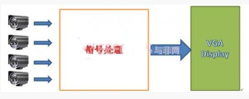
System Block Diagram
As can be seen from the figure, the system is mainly composed of three parts, namely camera (4), signal processing and display. The video signal collected by the camera is sampled and sent to the signal processing part for image processing and splicing, and finally sent to the VGA liquid crystal display.
3.2 System Solution Implementation
3.2.1 System hardware design
The system hardware design is shown below:

The camera captures the image signal and sends it to the ADV7184 for PAL signal decoding. The decoded digital signal is sent to the Spartan-6 FPGA for various image processing. After the completion, the RGB signal is sent to the ADV7123 for VGA format video output.
The ADV7184 is an integrated video decoder that automatically detects standard analog baseband TV signals compatible with NTSC, PAL and SECAM standards worldwide and converts them to 4:2 compatible with 16- or 8-bit CCIR 601/CCIR 656 : 2 component video data.
Spartan – 6 is the core device of this system and has the following features:
? Dedicated to low cost design
? Very low static and dynamic power consumption
Multi-voltage, multi-standard SelectIO? interface bank
? High efficiency DSP48A1 slice
? High performance arithmetic and signal processing
? Fast 18 x 18 multiplier and 48-bit accumulator
Pipeline and cascading functions
? Pre-adder for assisting filter applications
? Integrated memory controller module
• Dual triggers for LUTs designed for pipeline applications
? Block RAM with various granularities
? Low noise, high flexibility clock control
The ADV7123 is a high speed digital to analog converter with three high speed, 10-bit video DACs with complementary outputs, a standard TTL input and a high impedance, analog output current source for driving the VGA output. It has the following characteristics:
Throughput: 330 MSPS
Three-channel, 10-bit digital-to-analog converter
Spurious free dynamic range (SFDR)
RS-343A/RS-170 compatible output
Complementary output
DAC output current range: 2 mA to 26 mA
TTL compatible input
3.2.2 System Software Design
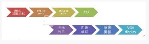
As shown in the figure, the viewing system works in eight steps. Among them, YCrCb to RGB system conversion, image denoising, shape correction, image cropping and splicing are all completed by FPGA.
After the ADV7184 is decoded, the YCrCb signal is output, and in order to facilitate the subsequent processing, it is converted into an RGB format. The conversion between YCrCb and RGB is as follows:
Since the camera (such as CCD, etc.) introduces noise more or less during imaging, especially when the brightness of the scene is insufficient, the noise is obvious, which will affect the subsequent processing work. Therefore, the converted signal needs to be denoised.
Since the fisheye lens is used, the edge portion is deformed, so shape correction is performed.
After the previous steps are processed, the image can be cropped and stitched. There are many ways to splicing images. Here you can calculate the shape required for each lens, and then cut and splicing according to the calculation results.
7.5 Mm Nano Tip,Smart Pen Infrared,Infrared Pen Touch,Slim Infrared Pen
Shenzhen Ruidian Technology CO., Ltd , https://www.wisonen.com