In the evolving landscape of power electronics, switching power supplies have become a cornerstone in the industry. As demand for energy-efficient solutions grows globally, the traditionally more cost-effective but less efficient linear power supply market is gradually shifting toward switching power supplies. During this transition, the power industry has been working hard to increase switching frequencies, aiming to meet the need for compact and high-performance power supplies. This shift has opened up new opportunities for switching power supplies, prompting design engineers to focus on optimizing their designs.
This article explores the fundamentals of selecting an inductor for a non-isolated switching power supply (SMPS). The examples provided are ideal for ultra-thin surface-mount applications, such as voltage regulation modules (VRMs) and point-of-load (POL) power supplies, though they do not cover systems based on larger backplanes.
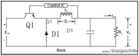
Figure 1: Typical buck topology power supply
The buck topology is widely used in systems where the output voltage is lower than the input. In a typical buck circuit, when the switch (Q1) is closed, current flows through the switch to the output, increasing at a rate determined by the inductance. According to Lenz's Law, the change in current through the inductor is equal to the voltage multiplied by the time interval, divided by the inductance value. As the current through the load resistor (RL) increases, so does the output voltage.
When a set voltage or current limit is reached, the control IC turns off the switch, reducing the magnetic field around the inductor and allowing the diode D1 to conduct, ensuring continuous current flow to the output until the switch is turned on again. This cycle repeats, with the control IC determining the switching frequency to regulate the output voltage to the desired level. Figure 2 illustrates the voltage and current waveforms across the inductor and other components during several switching cycles.
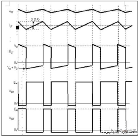
Figure 2: Switching power waveform of a buck topology power supply
The inductance value plays a crucial role in maintaining current flow to the load during the switch's off period. Therefore, calculating the minimum inductance required to sustain the output current is essential, especially under worst-case scenarios involving the lowest input voltage and highest output current. To determine the minimum inductance, the following parameters must be known:
- Input voltage range
- Output voltage and its tolerance
- Operating frequency (switching frequency)
- Inductor ripple current
- Operation mode (continuous or discontinuous)
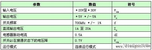
Table 1: Typical Step-Down Power System Specifications
The formula for calculating the inductance needed for a buck converter is:
L1 = Vo(1 - Vo/(Vin - Von)) / (f × dI)
In continuous mode: dI < ½ × I
To ensure the inductor performs reliably across all operating conditions, it's important to select values that maintain a stable ripple current even under the most challenging parameter combinations. For a buck converter, the worst-case scenario typically involves the lowest input voltage and switching frequency, along with the lowest output voltage. Designers can simulate these conditions to ensure the inductor meets the necessary performance requirements.
Using the data from Table 1, the minimum inductance can be calculated as follows:
L1(min) = Vo(min)(1 - Vo(min)/(Vin(min) - Von)) / (f(min) × dI)
L1(min) = 4.95V × (1 - 4.95V/(20V - 0.7V)) / (693,000Hz × 0.5A)
L1(min) = 10.6 μH
Thus, in this application, the inductor must have at least 10.6 μH of inductance and a current rating above the minimum 20A operating current, with a sufficient safety margin. Choosing an inductor with a lower inductance could cause the buck converter to fail in maintaining the output voltage within the specified range at maximum current.
Once the inductance value is determined, the actual inductor design must adhere to electrical standards, system size constraints, and installation methods. While many suppliers offer standard inductors, using off-the-shelf components may not always meet the specific performance and size requirements of the design. Fortunately, some manufacturers, such as Tyco Electronics’ CoEv Magnetic Components Division, provide custom engineering support to tailor inductors to exact specifications, helping optimize the design process and reduce development time. Leveraging industry expertise ensures faster time-to-market and better product performance.
samsung oca glass,samsung a12 oca glass,samsung a31 oca glass,samsung a51 oca glass,samsung m51 oca glass
Dongguan Jili Electronic Technology Co., Ltd. , https://www.jlglassoca.com