The use of IGBTs in any device will encounter IGBT selection and thermal design issues. After the two intuitive parameters of voltage stress and current stress are determined, the IGBT needs to be selected according to the loss and thermal cycle capability of the IGBT under the application conditions. Usually due to different operating conditions, the parameters given in the IGBT data sheet do not give an exact indication of the loss of the IGBT under the application conditions. A better method is to determine the difference between the measurement conditions of the parameters in the IGBT data sheet and the actual application environment through the measurement industry, and to introduce a simple measurement method for the loss of the IGBT.
Definition of IGBT parameters
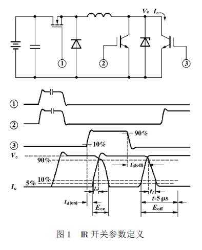
The IGBT switching parameters provided by the manufacturer are usually measured under purely inductive loads. Figures 1 and 2 are the circuits that measure the switching time of IR and TOSHIBA, respectively, and the waveforms that define the switching time. The common features are: Turn on the pure inductive load in the freewheeling state; Turn off the purely inductive load with the clamp diode. Some data sheets also show the energy loss of the switching process, which is also measured under the same conditions.
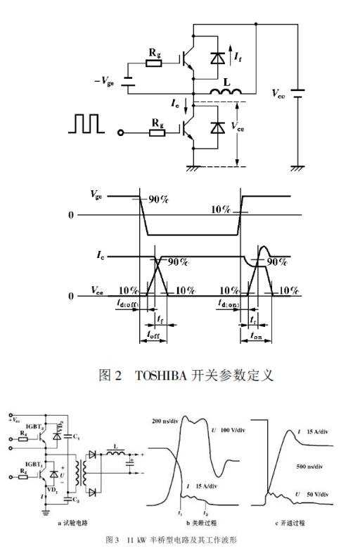
For a switching mode power supply that works in PWM mode and uses a transformer, its operation is quite different. Figure 3 shows an 11 kW half-bridge circuit and its operating waveform. The IGBT used is the GA75TS120U. As can be seen from the waveform, the current rise time tr is approximately 500 ns and the fall time tf is approximately 300 ns. However, in the data sheet, the current ramp time of the GA75TS120U is tr=100 ns and tf=80 ns, which is quite different from the actual working conditions. The reasons are mainly in the following two aspects:
(1) When opening, in Figure 3, due to the leakage inductance of the transformer, the IGBT actually turns on a zero-current inductive load, which is similar to zero current turn-on. The current rise rate is limited by the leakage-sensing charging speed, so the actual current rise time Tr does not depend entirely on the IGBT. In the data sheet, the pure inductive load in the freewheeling state is turned on. At the instant of turn-on, the IGBT must withstand the current in the inductor and also withstand the reverse recovery current of the freewheeling diode. The current rise rate is completely dependent on the turn-on of the IGBT. speed.
(2) When shutting down, the IGBT in Figure 3 is not shutting down one pure inductive load, but turning off one R - L type load (transformer and its load, which can be equivalent to R - from the primary side of the transformer) L-type load), its current fall time tf is slower than turning off the purely inductive load with clamp. Moreover, for a purely inductive load, the current of the IGBT begins to drop only after the collector voltage of the IGBT rises to the clamp value (see Figure 1, Figure 2), while the resistor-inductive load, the collector voltage and The current changes almost simultaneously (see Figure 3b waveform).
For the above reasons, the tr and tf of the IGBT in Figure 3 are both greater than the given value, but this does not mean the rise of the loss, because the switching loss also depends on the "overlap" of the voltage and current during the switching process, and in Figure 3 The "overlap" is obviously not as serious as in Figure 1 and Figure 2, so the overall loss will decrease.
Navigator speaker:
Navigator speaker is a kind of micro speaker unit which uses a diaphragm made of Mylar material. Mylar speakers are of ultrathin design and lightweight and clear voice. It is widely used in car electronics (GPS navigator, digital video recorder, radar detector-).
There are two types of Mylar speakers from the shapes:
1) Round shapes, we have products from 10mm to 57mm in diameter.
2) Oblong shape, we have products in sizes of 1510/1712/1813-..


FAQ
Q1. What is the MOQ?
XDEC: 2000pcs for one model.
Q2. What is the delivery lead time?
XDEC: 15 days for normal orders, 10 days for urgent orders.
Q3. What are the payment methods?
XDEC: T/T, PayPal, Western Union, Money Gram.
Q4. Can you offer samples for testing?
XDEC: Yes, we offer free samples.
Q5. How soon can you send samples?
XDEC: We can send samples in 3-5 days.
Navigator Speaker,Gps Speaker,Radar Speaker,Vehicle Navigation Speakers
Shenzhen Xuanda Electronics Co., Ltd. , https://www.xdecspeaker.com