Gases such as liquefied petroleum gas and coal gas are often used as fuels to cause poisoning and fire accidents due to leakage. There are many kinds of flammable gas leakage alarms, which are mainly used in industrial factories and mines. They are bulky and expensive, and it is difficult to promote them to households. Although there are some simple alarms, it is also complicated in structure and high in price. It is more difficult to promote to home. To this end, the problem of high cost of the device is solved by a combination of a simple digital and analog integrated circuit. Developed a compact combustible gas leak alarm, which has a simple structure and low cost (the main circuit component cost is only about 3 yuan, the total material cost of the outer casing and the power supply is only a dozen yuan), and the alarm sensitivity is within the performance range of the sensor. Any adjustable. The trial results show that the device is easy to use, the effect is very good, and the control function can be added only by simple improvement, and the device such as automatically turning on the fan can be conveniently realized. The flammable gas leakage alarm is not only suitable for families, but also suitable for industrial and mining enterprises, and its alarm sensitivity, alarm reminding function, reliability, etc. are superior to existing products.
1 System design optimization Compared with the current implementation of flammable gas leakage alarm technology is divided into two categories, one is based on single-chip smart alarm, including signal conditioning, A / D sampling and input and output circuits, etc., relatively complex . The other type is implemented entirely in hardware and the circuit is very complicated. Both of these technologies use more complex circuits to solve the initial alarm problem of the gas sensor. The reason for the initial alarm is that the conductivity of the sensor has not reached the steady state value when the sensor starts to power up, which leads to false alarm. After about 3 minutes, the conductivity of the sensor reaches the steady state value, and the alarm stops. In order to solve the initial alarm problem, the following two schemes can be adopted: 1) using a secondary alarm scheme, which uses the equivalent combustible gas concentration of the initial conductivity of the sensor as the first-stage alarm concentration, and only the alarm light is illuminated at this stage. The speaker does not ring. The second stage alarm is to turn on the audible alarm when the flammable gas leakage concentration reaches a critical dangerous concentration. This kind of scheme requires a more complicated two-stage comparison alarm circuit. The reminding power is not strong and unreliable, and the alarm sensitivity is not adjustable. 2) The alarm scheme with comparison or feedback delay is adopted, but the circuit is very complicated and the cost is high. Therefore, using hardware design to reduce costs is key. Here, a design scheme combining digital and analog integrated circuits is proposed to solve the problem of alarm and secondary alarm, and achieves good results.
2 Device selection and working principle Gas sensor has a wide variety of performance and performance. Here, the MQ-KC type sensor is used, which is a new type of resistance type gas sensing element, which can be used for leak detection alarms of natural gas, gas, and petroleum gas. It has high sensitivity, long-term stability, long life, low price, low power consumption, and easy to use battery. MQ-KC sensor principle: Connect the sensor to the specified load. At the initial stage of power-on, the conductivity of the sensor shows a high value and reaches the steady state value in about 3 minutes. If it is placed in a combustible gas with a certain concentration, its conductivity will increase. Within a certain range, the higher the concentration of combustible gas, the higher the conductivity of the sensor. If the sensor is connected in series with the load, the load will cause a voltage change. Read this change voltage, and compare and amplify to realize alarm and control functions.
3 hardware circuit design
3.1 Basic Alarm Circuit The MQ-KC type sensor has a rated supply voltage of 9 V and requires a load resistor to be connected. If the signal extraction and comparison circuit is designed with discrete components, the number of components is large, the cost is high, and the effect is not good. To this end, a single power supply 9 V power supply is used, and an integrated dual op amp with a certain driving capability is realized. Figure 1 shows the basic alarm circuit.
This article refers to the address: http://

In Figure 1, R1 is the load resistance required by the sensor, the resistance is 120 Ω, Vcc is 9 V supply voltage; A and B are LM358 dual op amps, A is a follower, which acts as a buffer to isolate the voltage on R1. VR1 is substantially all applied to the non-inverting input of comparator B. RW is the alarm sensitivity adjustment potentiometer. In steady state, the RW is adjusted so that the voltage applied to the inverting input of the comparator V- is slightly higher than the voltage VR1 on R1 at a steady state. The higher the voltage, the lower the alarm sensitivity. After powering up and bringing the sensor to steady state, MQ-KC is a stable fixed resistance value. When Vcc is constant, VR1 is basically a fixed value and remains unchanged. When a flammable gas leaks, the sensor is exposed to flammable gas, causing its conductivity to rise, and the resistance to drop, causing VR1 to rise. When VR1 is higher than V-, the comparator outputs a voltage greater than 7 V, thereby making the buzzer HA emits an alarm sound of drops and drops. If this voltage is used to control a relay, the control function can be realized. In order to improve the anti-interference ability, a filter capacitor can be connected in parallel with the V- terminal of R1 and B, respectively.
The values ​​of R1, R2 and RW should not be too small to reduce the power supply current. The value can be estimated by equation (1), and RW can be temporarily ignored when estimating. 
Let V-=VR1 take R3=2 kΩ, and know that Vcc=9 V, we can find R2. The device has R2 = 10 kΩ and RW = 10 kΩ.
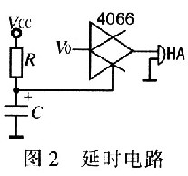
Substantially less than the alarm circuit shown in FIG. 1 3.2 initial alarm circuit: powering the outset, the sensor has not yet reached a steady state, the resistance value is small, VRl larger, resulting in false alarm buzzer HA. In order to solve this problem, a digital signal controlled analog switch is used, and its control signal adopts a simple capacitor charging delay circuit. The schematic diagram is shown in FIG. 2 . The output V0 of comparator B in Figure 1 is applied to the input of analog switch 4066, and the output of the switch is connected to buzzer HA. At initial power-on, the voltage VC on capacitor C is 0, and 4066 is not conducting. No matter how high the V0 value is, HA will not alarm. As the capacitor is charged, the VC continues to rise. When the control threshold threshold of 4066 is reached, the 4066 is turned on, and the alarm state can be entered. The delay time is charged when the capacitor is charged so that its voltage reaches the threshold threshold of 4066. The values ​​of capacitor C and resistor R can be determined according to the delay requirements. For reliability, take RC = 1/2T, and T is the initial stabilization time of the sensor. The device takes R=l MΩ, C=100μF, which can achieve reliable delay.
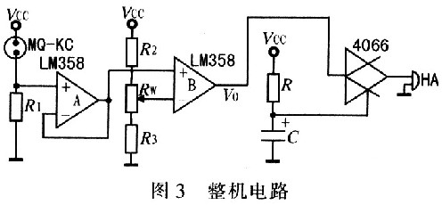
3.3 The whole machine hardware circuit design and debugging combine the above two circuits to form the whole machine circuit, as shown in Figure 3. In order to make V- stable, R1 and R2 should use precision metal film resistors. After the device is warmed up for 3 minutes, the voltage VR1 on R1 is measured with a multimeter and measured to be 1.7 V. To make the alarm concentration of the device x%, if possible, place the sensor in a combustible gas with a concentration of x% (monitored by a gas component analyzer), and then measure the voltage on R1 to obtain VR1 after 10 s. Adjust RW to adjust V- to slightly less than VR1. In normal use, when the flammable gas leakage concentration reaches the calibration concentration x%, the device will alarm. If the control device is added, the fan can be turned on or the valve can be closed. When there is no condition, adjust RW and adjust V- to slightly larger than VE1 to ensure no alarm in normal air environment. Then install the device next to the gas-fired cooker, open the cooker switch, blow out the flame, a small amount of flammable gas leaks, the device should alarm. To increase the alarm concentration, adjust RW to increase V-, and vice versa.
3.4 Power Supply Design The unit's mains supply current is less than 20 mA, so it can be powered by a 9 V battery. The prototype is powered by AC 220 V and is regulated by a 7809 three-terminal regulator.
4 trial experiment and results
4.1 Trial Results The device was placed in the kitchen and warmed up for 3 minutes with no initial alarm. Close the kitchen door and release the right amount of gas. After a few seconds, the device will start to alarm and then move the device away from the site. The alarm will stop after about 30 s. In the normal air kitchen, the device is preheated for 3 minutes, placed on the side of the gas stove, the stove switch is turned on, the flame is blown out, and the device starts to alarm after a few seconds. When the kitchen still has gas, it will continue to alarm. , put it outside the window, it can recover faster and stop the alarm.
4.2 Application and installation The device can be used not only for the gas leakage alarm of industrial and mining enterprises, but also because of its low cost, it can also be extended to ordinary households as a leakage alarm for gas bathing devices and kitchen gas. An automatic leak alarm can be achieved by installing it near a gas appliance (with the best effect within 1 m). When installing, be careful not to place the unit at the vent.
5 Conclusion This device uses a digitally controlled integrated analog switch and a RC capacitor to solve the initial false alarm problem of the flammable gas alarm device. The signal extraction, comparison and alarm drive are realized by a single-supply dual-integrated op amp. The device alarm sensitivity is arbitrarily adjustable within the sensor performance range. The following performance is achieved: power consumption is less than 0.3W; sensitivity V1/V0>2; response time is less than lO s: recovery time is less than 30 s. The flammable gas alarm device uses a combination of digital and analog integrated circuits, which greatly reduces the number of components, thereby improving the stability and reliability of the device, and making the component cost of the main circuit less than 3 yuan. It makes it more cost-effective, and can further improve the alarm device according to user needs and specific conditions. Adding a level of control circuit can be achieved by adding a level of relay drive to the output of comparator B.
Thanks to the diversified sizes and dimensions of Lfp Battery cells, we are enabled to build up a complete set of battery packs with working voltage range from 12V up to 600V. Please do not hesitate to contact us if you are in need of electric power for automotive or energy storage solution. We will provide you with a great variety of customized services.
Customized Lifepo4 Lithium Battery
Customized Lifepo4 Lithium Battery,Lifepo4 Lithium Battery,Customized Rechargeable Battery,Customized Lithium Battery
FORZATEC CO., LIMITED , http://www.forzatec.com