As an indispensable part of the car, the throttle directly affects the safety of the car. Since the 21st century, most cars have replaced the conventional throttle with an electronic throttle. Compared with the old-fashioned pull-throttle, the electronic throttle controls the electronic signal by the depth of the accelerator pedal, so that the engine provides the matching power. The biggest feature is that the throttle opening can be controlled by the ECU. When the position of the accelerator pedal changes, the signal output from the electronic throttle can be used as a basis for measuring the accuracy of the electronic throttle automatic control. The electronic throttle detection system uses various schemes to evaluate the quality and reliability of the electronic throttle based on these real-time signals. Its performance testing.
1 System test items and types The main function of the electronic throttle is to convert the angle at which the driver steps on the accelerator pedal into a voltage signal proportional to it, and at the same time make various special positions of the accelerator pedal into contact switches, idling, high load, Engine operating conditions such as acceleration and deceleration become electrical pulse signals are sent to the controller ECU of the electronically controlled engine to achieve optimal automatic control of fuel supply, fuel injection and shifting. The detection system is based on the type of electronic throttle, mainly adopting five kinds of detection schemes: specifically including dual signal detection, dual signal plus switching quantity detection, single signal detection, single signal plus switching quantity detection, and electronic throttle detection with KD device.
1.1 System Test Items Most electronic throttles need to detect information such as synchronization, linearity, pedal force, etc. The specific definitions of these test items are as follows:
(1) Synchronization degree: The throttle outputs the equality of two signal values ​​at a certain stroke angle.
(2) Linearity: The difference between the theoretical voltage value of the throttle signal at a certain stroke angle and the actual voltage value.
(3) Free-stroke angle: refers to the pedal stroke angle at which the signal continues to change when the pedal begins to change angle.
(4) Pedal force: including pressure and elasticity, is the force curve of the pedal from idle speed to full stroke, and then from full stroke to idle speed.
(5) Throttle signal curve: including the idle signal and full stroke signal, the voltage output signal curve of the accelerator pedal from idle speed to full stroke.
(6) Hysteresis: At a given angle, the output pressure in two different directions of rotation is measured, and the hysteresis effect is the difference between the two output pressures. The maximum acceptable gap is 1% for Ua taxis.
(7) Repeatability: Under the same conditions, after 10 complete round trips, the recorded voltage difference cannot exceed the sensor with a given temperature of (23 ± 5) °C and any point in the same direction. O. 5%.
(8) Tilt error: The formula is as follows: 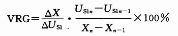
Where: VGR is the variable about the slope; △X is the distance between the bending points, the unit is mm; ΔUs1 is the difference between the full load Vs1 and the slow speed Vs1; Us1n and Us1n-1 are expressed at the position n and The voltage at n-1; Xn and Xn-1 represent the travel at position n and n-1.
1.2 System Detection Type The electronic throttle with KD device is the most complicated throttle in the inspection project. In the throttle detection pattern with the angle as the abscissa, the throttle of the KD device needs to be converted into a stroke display, and the stroke can be calculated according to the formula L=2*R*sin(Θ/2). Where: L is the stroke; R is the radius of rotation; Θ is the angle of rotation. Where R is the set value and Θ is the angle sensor detection value. In addition, specific determination conditions for the range of idle position, force, stroke and voltage value can be referred to FIG. 1 and FIG. Figure 1 is a graph of the throttle ideal force with a KD device. It can be seen from the figure that the starting point of the KD throttle (2 mm on the abscissa) is the F1 point, the sensing point (at the 50 mm abscissa) is the F2 point, and the maximum force point is the F3 point.
This article refers to the address: http://
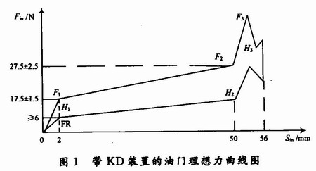
For example, if there is a KD force maximum point in the set 50~56 mm stroke, determine whether the value of the point force meets the setting requirement, and determine whether the distance from the set distance of 50 mm is less than the set value (in Figure 2 2 mm); from the KD force maximum point corresponding stroke plus 0.7 mm rear stroke position corresponding to the output electrical signal is 4.1 V (set value); from the output electrical signal 4.1 V position to the mechanical limit Whether the position of the bit position (ie, the maximum stroke position is 56 mm) is greater than 3.3 mm. Fig. 2 is a graph showing the determination condition of the throttle signal with the KD device.
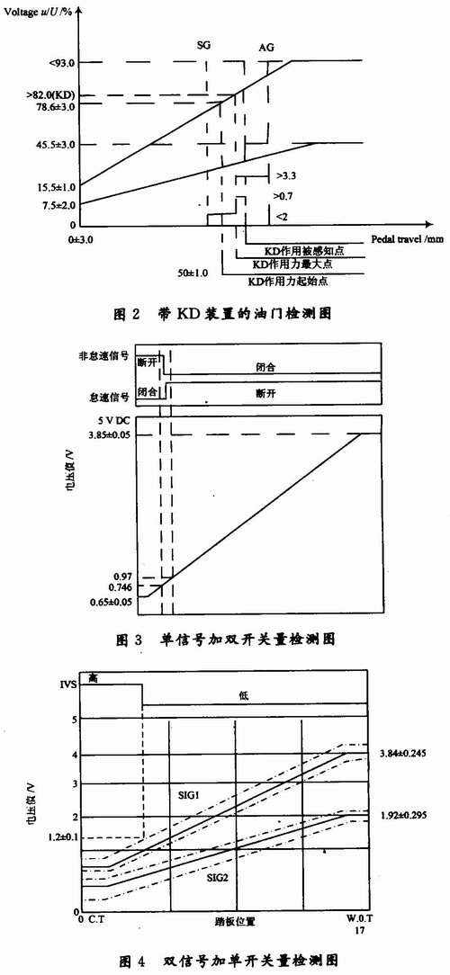
The single signal detection function mainly detects the synchronization degree of the main signal voltage SIG1, and whether the linearity or the like is within the set range. The single signal plus switching detection is based on the single signal detection to increase the switching amount detection, as shown in Figure 3.
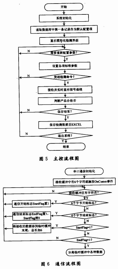
The dual signal detection mainly detects whether the synchronization degree and linearity of the two voltage signals SIG1 and SIG2 are within the set range, and ensures that the measured signal curve is between the ideal signal curves. In addition, there are specific detection regulations for the idle speed of the idle travel, etc., and the standard settings are made separately depending on the type of throttle. The dual signal plus switching detection is mainly based on the above two-signal detection to add a switch detection, detect the change of the switch voltage within the set voltage range, and then judge its correctness, as shown in Figure 4.
2 System Communication Protocol This system uses the serial communication protocol. The baud rate is set to 9 600 b/s by default. This item can be adjusted. The format of the character is set to 1 start bit, 8 data bits and 2 stop bits, and the middle 8 bits are valid data.
The host computer issues the command format: 0xAA + command + check code (and 0 check). The content of the instruction is a single test instruction: 0x91; the cyclic test instruction: 0x92; the end of the test: 0x94.
The data format of each single test lower computer is: 6 0xBB bytes as the start mark of the data, and the middle is the collected real-time data (data packet transmission, one cycle of a set of data, each set of data is incremented by angle O.5 degrees For a value), the last is 6 0xCC bytes as the end of the data. The data content is the original value of the 10-bit A/D acquisition with a reference voltage of 5 V. The real-time data format collected in the middle is the data type (6 binary bits) + data content (10 binary bits). The specific definition of some data types is shown in Table 1.

3 system software implementation
3.1 Software implementation of the main function module The electronic throttle detection system consists of two parts: the upper computer software and the lower computer software and hardware. The lower computer software is written in C language, and the specific hardware design circuit and software programming part will not be described in detail here. The upper computer software consists of three main functional modules, which are throttle communication module, parameter setting module and information management module. The overall design flow is shown in Figure 5. First, the system initialization, including serial communication initialization, product parameter setting initialization (read the first record in the background database as the default setting data), wait for the host computer to send detection commands, the lower computer transmits real-time signal detection data according to the protocol verification, At the same time, the real-time signal curve is displayed, and then the product is judged according to the setting conditions, and the result is stored and processed.
In the communication module, the Microsoft communication control MSComm is directly adopted. Taking into account the speed of serial port data transmission and reception, the program here uses the method of receiving and post-processing in real-time data to prevent the loss of real-time data of serial communication. The specific program implementation process is shown in Figure 6.
3.2 Detection system Host computer main interface This test system uses VC++ as the host computer development tool, and uses the graphical interface to complete and visually reflect its detection process and detection results. At the same time, the background uses ACCESS to manage and store a large amount of data for testing. The operator can view the test situation and demonstrate the online test process, and can update the database at any time to test multiple types of throttle.
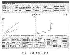
In the command selection area of ​​the menu, when the product information parameter is clicked, the product setting interface appears, and the throttle standard parameters are set. The current information after the configuration will appear in the display setting information interface; when the historical record is clicked, the previous setting appears. And check the product part number, click any one of them, the display setting information interface will display the parameters of the product; when click print save, save the current product setting information, test results and current interface to Excel. The main interface of the throttle detection with KD device is shown in Figure 7. The left side of the middle display area is the signal display area, the right side is the throttle pressure and elastic display area; below the interface is the detection result display area, click the “Display Settings Information†button. View the current product settings information, click on the "Synchronization Graph" to view the throttle synchronization curve.
4 Conclusion Based on the real-time communication and data processing methods between PC and MCU in VC++ environment, an electronic throttle detection system is designed. Make full use of VC++'s powerful data analysis capabilities, greatly improving development efficiency. According to the different types and types of electronic throttles, five kinds of detection schemes are mainly used to detect the synchronization degree, linearity, and idle angle of the throttle voltage at the idle speed. Finally, the real-time data of the electronic throttle is obtained through the acquisition of real-time data. The graph directly reflects the characteristics of the electric signal inside the throttle, ensuring safe and reliable detection purposes, and has certain practicability. Currently, the electronic throttle detection system has been put into use. Practice shows that the test system is reliable in design and has good test results.
Mini Circuit breakers, also named as the air switch which have a short for arc extinguishing device. It is a switch role, and also is a automatic protection of low-voltage electrical distribution. Its role is equivalent to the combination of switch. Fuse. Thermal Relay and other electrical components. It mainly used for short circuit and overload protection. Generally, According to the poles, Mini Circuit Breaker can be divided into 1P , 1P+N , 2P, 3P and 4P.
Miniature Circuit Breaker,Electronics Miniature Circuits Breaker,Automatic Miniature Circuit Breaker,Mini Circuit Breaker
Wenzhou Korlen Electric Appliances Co., Ltd. , http://www.korlenelectric.com