 With the increasing demand for energy-saving, environmental protection and comfort of refrigerators, more and more intelligent control technologies have been introduced into refrigerators. Embedded smart home appliances are also referred to as smart home appliances. In such household appliances, the man-machine interface is friendly and convenient, and the single chip microcomputer controls the basic functions of the household appliances, and at the same time simulates the human intelligent activity process. In the control process, various intelligent activities are combined to perform the necessary processing, which greatly improves the quality and performance of household appliances, and produces more excellent control effects, so that people can get more ideal services.
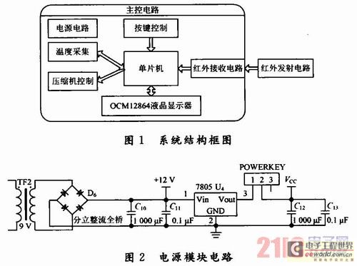
 1 system structure The system takes the STC89C516RD microcontroller as the control core, uses the 220 V power supply, through the liquid crystal display current time as well as by the temperature sensor gathering refrigerating room, the freezer room and the outdoor temperature. The time and temperature values ​​of each room can be set by pressing a button. Since the system integrates an infrared remote control function, the user can also remotely set the time and temperature of each room through the remote controller. System block diagram shown in Figure 1.
2 system hardware implementation 2.1 Power Module In the power module design, the 220 V AC voltage is stepped down by a 9 V transformer, and then through a rectifier bridge circuit, after rectification to get a DC voltage of 12 V, due to the power requirements of the system Not high, only need 5 V, so use a 7805 regulator to generate a voltage of +5 V for the microcontroller and LCD display. The power circuit is shown in Figure 2.
2.2 Temperature acquisition module uses DS18B20 temperature sensor to complete the temperature acquisition. The DS18B20 is a one-wire digital temperature sensor manufactured by Dallas. It is a new generation of smart temperature sensor that adapts to a microprocessor. It integrates temperature sensing, signal conversion, and A/D conversion on a single chip, and is packaged in a TO-92 package. Its temperature measurement range is -55 ~ +125 °C, programmable 9 ~ 12-bit conversion accuracy, temperature resolution up to 0.062 5 °C. This system uses three DS18B20 to separately measure the temperature of the refrigerating chamber, the temperature of the freezing chamber and the room temperature.
2.3 Button Control Module The keyboard control circuit is composed of 4 independent buttons connected with the I/O of the SCM. It is used to switch the LCD display interface and adjust various parameter values. The key functions and the corresponding relationship with the I/O port are as follows:
[ON/OFF] temperature, time switch key - (P13)
[Mode] Select Key - (P12)
[—] Temperature or time minus 1—(P11)
[+] Temperature or time plus 1 - (P10)
2.4 The wireless control module adopts the chipset PT2262-IR and PT2272 to encode and decode, and the PT2262-IR and the infrared transmitting tube constitute a wireless transmitting part and transmit a 38 kHz modulated signal with key information. The PT2272 and 38 kHz wireless receiver module LT0038 form a wireless receiver. The module wirelessly controls the switch by transmitting and receiving radio waves. The circuit is easy to implement and cost-effective, and the circuits and parameters involved have been tested. The device has a small size, low power consumption, low cost, remote control distance of up to 10 m.
2.5 Compressor control module Compressor drive circuit is mainly achieved through the control of the single-chip microcomputer to the relay. A relay is an "automatic switch" that uses a small current to control a large current, so it plays a role in the circuit such as automatic regulation, safety protection, and conversion circuits. Because it is necessary to use a single-chip microcomputer to directly control the compressor, the single-chip microcomputer is powered by +5 V, and the compressor is powered by 220 V. Therefore, the relay must be used as an isolation circuit to separate the high and low voltages. Use P1.6 mouth to control the relay, thus indirectly play the role of controlling the compressor switch.
2.6 LCD Module Selection OCM12864 liquid crystal display, OCM12864 liquid crystal display module data input / output port 7 to 14 feet connected to the microcontroller P0 port, used to transfer data or instructions; read / write select pin connected to the P2.1, high-power Normally read data, write data when low level; data/instruction select pin is connected with P2.0, when high level, send data of P0 port to display RAM, when low level, send data of P0 port to instruction register to execute ; Read and write enable signal terminal E and P2.2 connected, active high, falling edge lock data. The reset signal is connected to P2.5, which is active low. The chip select signal CS1 is connected to P2.3 and is active high. The chip select signal CS2 is connected to P2.4 and is active high. The LCD drive voltage is V0. Apply a 10 kΩ adjustable resistor between the LCD drive power supply and the +5 V positive power supply VDD. By adjusting the resistance, you can change the brightness and darkness of the LCD display.
3 system software to achieve the entire software part is completed by the C51 language, mainly includes the following four sub-program modules: temperature acquisition module, clock module, liquid crystal display module, keyboard control module. Each subroutine module is written and debugged separately, then each subroutine module is jointly debugged, and finally the program is programmed into the ROM of the single chip microcomputer to run offline.
4 Debugging Simulation and Conclusions After debugging, the program is loaded on the hardware board and runs at full speed. The initial screen shows the current date and time. The date and time can be adjusted by pressing the key. After the mode switch button is pressed, the display interface is switched to the temperature display mode, and the temperatures of the refrigerating room, the freezing room, and the outdoor are respectively displayed on the interface. The temperature value can be set by pressing the button. When the actual temperature is greater than the set temperature, the MCU will start the compressor to reduce the temperature. At this time, the LED emits light, indicating that the compressor is working until the actual temperature equals the set temperature and the compressor stops working.
Optical Fiber Passive Components
Optical Fiber Passive Components,High Quality Optical Fiber Passive Component,Electronic Components & Supplies, Fibre Optic Passive Components
Optical test instruments,Fiber Optic Equipment Co., Lt d , http://www.nbopticfiber.com