introduction
DSP has the advantages of fast processing speed and powerful functions. The design uses TMS320F2812 as the control chip and HS12864 liquid crystal display module as the display device, which realizes the menu display of harmonic detection data and the display of harmonic spectrum lines. In order to solve the timing matching problem between fast DSP chip and slow liquid crystal display device, F2812 rich I/O port is used to realize timing control and data communication with HS12864, and the power between high speed DSP and slow speed liquid crystal module is solved. Flat conversion problems, as well as interface synchronization issues.
1 TMS320F2812 Features
The TMS320F2812 is TI's latest digital signal processor, a fixed-point digital signal processor based on the TMS320C2xx core. A variety of advanced peripherals are integrated into the device to provide a good platform for the implementation of motors and other applications. At the same time, the code and instructions are fully compatible with the F24x series, ensuring continuity of project or product design. The chip uses a high-performance 32-bit central processing unit, Harvard architecture, high-performance static CMOS technology, frequency up to 150MHz (clock cycle up to 6.67ns); with an external memory interface, can expand up to 1MB of space. On-chip 18KRAM, 128kflash memory, 128-bit key; internal integrated timer, event manager, SPI, SCI, CAN, AD and other rich on-chip peripherals.
2 HS12864 LCD Monitor Features
The biggest feature of the T6963C is its unique hardware initialization setting function. The parameters required for the display driver such as duty cycle, number of bytes transferred by the drive/line and font of the characters are set by the pin level. Initialization is already on power-up. almost done. The font selection is realized by selectively transmitting a byte of 8-bit font data during display data transmission. The T6963C control series LCD has selected FS0=0, FS1 is introduced to the MCU interface, ie FS, and the user passes FS. Connect high or low to achieve 6&TImes; 8 or 8 & TImes; 8 font selection. T6963C has 128 kinds of 5&TImes; 8 dot matrix ASCII character font library CGROM, character code is 00H~07H, and allows the user to open a user-defined character 8×8 dot matrix font library CGROM in the display memory. While using the internal CGROM, CGRAM can also be supported, and the character code is defined in 80H~FFH. The T6963C can manage 64k of display memory, and the actual module only has 32k of memory. The T6963C divides 32k of memory into text display, graphic display, text attribute area or custom character library area.
3 hardware interface design
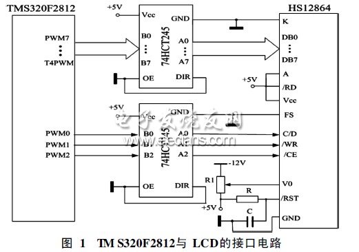
The TMS320F2812 has two ways to access the LCD module: bus mode and I/O port mode. Since the processing speed of the liquid crystal module is much slower than that of the DSP, in order to match the speed of the two, a certain delay must be added to meet the requirements. Therefore, the I/O method is used in the design, and the digital I/O of the DSP is used. The mouth controls the liquid crystal display module. The digital I/O port of the TMS320F2812 chip operates at 3.3V, and the operating voltage of the LCD module is 5V. In order to ensure the normal operation of the liquid crystal and the DSP chip will not be burnt due to excessive pin voltage, The level shifter is connected to the level converter. Since the system only writes signals to the liquid crystal module, as long as the voltage conversion of 3.3V to 5V is realized, the design uses two 74HCT245 as the level conversion chip.
This design uses 11 I/O ports of DSP, which are GPIOA0~GPIOA2 (PWM1~PWM2), GPIOB0~GPIOB7 (PWM7~T4PWM), pass level change devices, they are respectively C/D and /RW of LCD. , /CE, DB0~DB7 pins are connected. As shown in Figure 1, the write operation of the liquid crystal can be realized by setting the high and low of GPIOA0~GPIOA2. The system only writes to the liquid crystal, so the liquid crystal /RD pin is directly high, LCD FS The foot is directly connected to the low (ground) display 8×8 font, the /RST end is connected with the capacitor and the resistor, and then connected to the ground and the +5V power supply respectively, and the V0 is connected with the potentiometer and the negative pressure for adjusting the liquid crystal screen. Display contrast.
Zinc selenide (ZnSe) is a very good infrared material with a wide range of light transmission, from 0.5 microns to 19 microns. Because zinc selenide has a very low absorption coefficient in the 1064nm band, has good imaging characteristics and thermal shock characteristics, it is often used as a lens and window for carbon dioxide lasers. At the same time, the excellent optical properties of zinc selenide lenses are also widely used as windows, optical lenses and Optical Prisms of high-definition forward-looking infrared systems.
Laser Focusing Lens,Optical Lasers,Laser Lens,Lasers In Optics
Changchun Realpoo Photoelectric Co., Ltd. , https://www.optics-realpoo.com