Abstract SG3525 is a monolithic integrated PWM control chip. In this paper, SG3525 is used as the control core. A high-frequency inverter, soft switch and capacitor compensation technology is used to design a prototype of non-contact low-power power transmission system with overcurrent protection. Experiments show that when the distance between the primary and secondary sides of the system is 1 mm, the power transmission efficiency can reach 78.9%, achieving efficient energy transmission.
This article refers to the address: http://
Traditional power transmission is mainly transmitted through wires, and direct physical contact between the power supply and the load is required. In daily life, with the increase of electrical equipment, direct physical contact is both inconvenient and increases the safety hazard of electricity consumption. In addition, with the development of artificial organs and underwater detection devices, non-contact charging has become an urgent need.
Since the non-contact power transmission is loosely coupled, the power transmission efficiency is low. Generally, a high frequency inverter circuit is used to increase the transmission efficiency by increasing the frequency. In high-frequency inverter circuits, many control chips are expensive and complicated to use. The SG3525 is a control chip for driving n-channel power MOSFETs from General Electric Semiconductor of the United States. It can adjust the frequency of the corresponding parameters and adjust the dead time. Moreover, the chip has a soft start and a close end for overcurrent protection. The peripheral circuit is simple, each piece is less than 1 yuan, and is widely used in switching power supplies, and has less application in non-contact power transmission. In this paper, SG3525 is used as the control core, and a non-contact low-power power transmission system with overcurrent protection is designed.
1 system topology and working principle
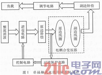
The non-contact power transmission system mainly consists of two parts: energy emission and energy reception. The system topology is shown in Figure 1. The energy emitting part comprises a rectifying filter, a control circuit, an inverter circuit, a primary side compensation and a primary winding, and converts the electric energy into magnetic energy; the energy receiving part comprises a secondary winding, a secondary side compensation and regulation circuit, and converts the magnetic energy into electric energy. The working principle of non-contact power transmission is: power frequency AC power is stepped down, full bridge rectifier circuit, filter circuit becomes available DC power, high frequency alternating current is generated by high frequency inverter circuit, and low frequency alternating current is completed. The high-frequency alternating current is converted, and the generated high-frequency alternating current is supplied to the primary side coil, thereby generating a changing magnetic field in the primary side coil, and the secondary side coil receives the electric energy through the inductive coupling, and after adjusting the circuit by rectifying and filtering, the parameter can be supplied to the load appropriately. DC power.
2 system main components design
Due to the low frequency of the power frequency, the efficiency of non-contact power transmission is limited. The inverter circuit can generate high-frequency alternating current, which becomes an important part of the system. The control circuit is used to control the frequency of the inverter circuit, and the protection signal is realized by receiving the feedback signal of the detection circuit.
2.1 Control circuit design
The control circuit is used to generate a high frequency PWM (Pulse Width Modulation) signal to control the conduction of the corresponding switch tube, thereby implementing DC-AC conversion. This design uses SG3525 as the control core. SG3525 is a monolithic integrated PWM control chip with excellent performance, complete functions and versatility. It is simple and reliable. The output driver is push-pull output form, which enhances the driving capability. The internal undervoltage lockout circuit is included. , soft start control circuit, PWM latch, frequency adjustable, and can limit the maximum duty cycle, peripheral circuit design shown in Figure 2.
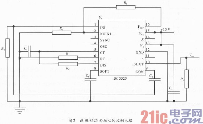
By connecting resistors and capacitors between pins 1 and 9, a PI regulator can be constructed to compensate the amplitude and phase response characteristics of the system. The 8-pin external capacitor C3 is charged by an internal 50μA constant current source for soft-start function. The 10-pin is connected to the feedback signal and is low during normal operation. When the input is high, the external capacitor of pin 8 starts to discharge and the SG3525 stops working. When the 10 feet return to low level, the 8 feet are charged and the chip works again.
The output frequency of the system is related to the 5-pin external capacitor C1, the 6-pin external resistor R3 and the dead-band resistor R4. Adjusting its parameters can produce a rectangular wave of 100-400 kHz. The dead time can be adjusted by adjusting the dead band resistance R4. frequency
Where 0.001 μF ≤ C1 ≤ O. 2 μF; 2 k Ω ≤ R3 ≤ 150 kΩ; R4 ≤ 500 Ω.
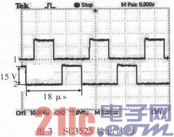
The design choice is R4=100 Ω, C1=0.01μF, R3=2 kΩ, and the calculated frequency is 58.8 kHz. The complementary pulse waveforms are output at pins 11 and 14, as shown in Figure 3.
2.2 Series full-bridge resonant inverter circuit design
The inverter circuit uses a full-bridge inverter circuit, and the drive circuit uses two IR2111s. IR2111 is a gate driver integrated chip for power MOSFET and IGBT. The peripheral circuit is simple and has a built-in 650 ns dead time to prevent the upper and lower tubes from conducting directly. The complementary pulse signals output by the 11th and 14th pins of the SG3525 are respectively input to the signal input terminals of the two IR2111, as shown in A and B in FIG. Each piece of IR2111 can generate two inverted pulse signals to control the on and off of the full-bridge inverter circuits Q1, Q2, Q3, and Q4.
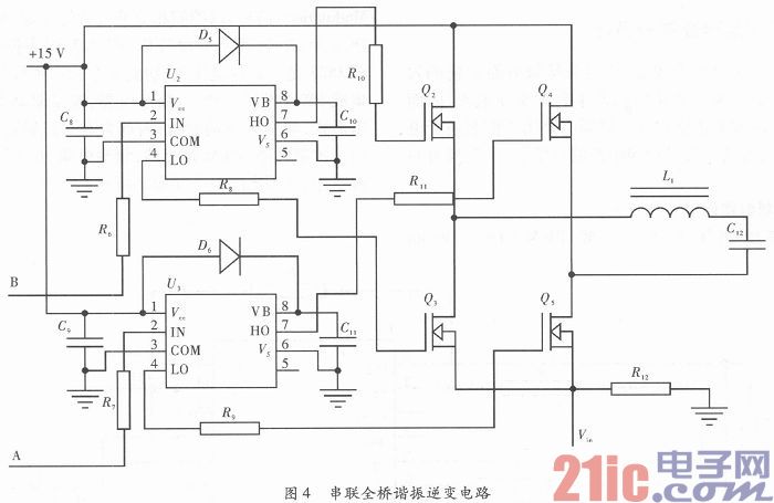
In the full-bridge inverter circuit, the switching device has a large loss due to the high frequency. In order to reduce the switching loss, soft switching technology is needed. As shown in Figure 4, the switching trajectory of the power MOSFET is shaped by the resonance of L1 and C12 to achieve zero voltage or zero current shutdown, thereby reducing switching losses.
2.3 Overcurrent protection circuit design
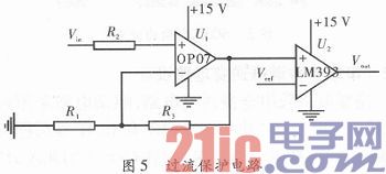
In the full-bridge resonant inverter circuit, a current sampling resistor is connected in series, as shown by R12 in FIG. Sampling of the current in the circuit can be achieved by measuring the voltage across the sampling resistor. The collected voltage is fed back to the control chip SG3525 to implement overcurrent protection of the circuit, as shown in FIG. Since the voltage is small, it needs to be amplified by an operational amplifier. The amplified voltage is compared with the reference voltage, and the comparison result is input to pin 10 of the SG3525. If the amplified sampling voltage is less than the reference voltage, it outputs a low level; if it is greater than the reference voltage, it outputs a high level, so that the SG3525 is turned off, and the overcurrent protection function is realized.
3 design of other parts of the system
3.1 Analysis of primary and secondary capacitor compensation
In the non-contact power transmission system, the original and secondary sides of the transformer are separated from each other, the coupling coefficient is small, and the coupling mode of the transformer is loosely coupled. In this case, the transmission efficiency of the transformer is low. In order to improve the power transmission capability of the transformer and minimize the reactive power consumed by the system, the compensation capacitive reactance is generally used to balance the inductive reactance in the circuit. Capacitor compensation has two types: series compensation and parallel compensation. Due to the different compensation methods, the compensation effect is not the same.
Since the transformer is loosely coupled, a coupled inductor model analysis is required. The following is an example of the series compensation of the primary and secondary capacitors. The coupled inductor model is shown in Figure 6.
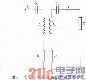
Reflection impedance from the secondary side to the primary side

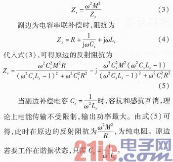
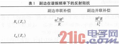
Table 1 shows the reflection impedance at the primary side of the secondary side using a capacitor string and parallel compensation at the resonant frequency. It can be seen from Table 1 that when the secondary side is compensated in parallel with the capacitor, the reflection resistance on the primary side is non-pure resistance, and the primary side design is more complicated. Therefore, this design uses the original and secondary side series capacitor compensation.
3.2 Loosely coupled transformer design
(1) The choice of coupler. A simple coil has a small inductance value, and the inductance value can be increased by winding the coil on the core material. The shape of the coupler depends on the shape of the core structure. Common core structures are U-shaped, E-shaped, RM-type, and EI-type, and their sensing characteristics are different. Choosing the right core structure and materials can increase the transmission efficiency of the system. In order to reduce the core loss, a magnetic core material with high magnetic permeability, small coercive force, and high saturation magnetic induction strength should be selected. This design uses a commonly used EE type ferrite core.
(2) Choice of wire diameter. The coil is wound on the core material. When the high-frequency alternating current is passed, a "skin effect" occurs, so that the high-frequency alternating current resistance is greater than the direct current resistance, and the higher the alternating frequency, the smaller the penetration depth. In order to ensure that the high frequency current completely penetrates the wire, the diameter of the wire should not be greater than twice the penetration depth. Penetration depth
The conductivity of the copper wire is γ=5.8×10⁷s·m-1, and the magnetic permeability μ=4π×10-7H·m-1. When the switching frequency is 60 kHz, the formula can be obtained as Δ=0.27 mm, so The diameter of the copper wire should be <0.54 mm. Due to the small power, the current density of the wire can be J=3×10⁻⁶A·m-2, and the effective value of the current is I=1 A, then the cross-sectional area of ​​the wire
. Thus, a copper wire having a wire diameter of 0.5 mm can be selected and wound.
4 system implementation and performance testing
Designed with SC3525 as the control core, the design working frequency is 58.8 kHz, the measured frequency is 56.7 kHz, the drive chip is IR2111, the switch tube is IRF540n, the magnetic core is soft ferrite core EE42, and the coil is made of copper with a diameter of 0.5 mm. The wires are wound in double strands, and the primary side is wound 20 times, the inductance value is 47.9 μH, the secondary side is wound 21 turns, and the inductance value is 50.8 μH.
The system input DC voltage is 15 V, and the load is 100 Ω. When the distance between the primary and secondary sides is 1 mm, the measured secondary current is 0.15 A, and the primary current is 0.19 A. The calculated power transmission efficiency is 78.9%. When the distance between the primary and secondary sides is 3 mm, the power transmission efficiency is 53.7%. As the distance increases, the power transfer efficiency will decrease. When the distance between the primary and secondary sides is 7 mm, the power transmission efficiency is low, and the system is considered to be stopped.
5 Conclusion
The experimental results show that the designed low-power non-contact power transmission system with SG3525 as the control core is simple and reliable, and can realize efficient transmission of electric energy. If the received voltage is rectified and filtered and the voltage regulator tube 7805 is supplied to the single-cell lithium battery management chip TL4906, wireless charging of the single-cell lithium battery can be realized.
19V Plug in AC/DC Switching Power Supply were widely used for any small power device, such as CCTV Cameras, wireless routers, LED strip, ADSL cats, HUB, switches, security cameras, audio/video power supply. For 19V wall mount power supply, the maximum output current is 1.89A,total 36W output. Our power adaptor meets different certificates for different countries` request – like UL list/CCC-CQC/ PES/SAA/C-TICK/CB/GB certificate. All our switching power supplies were getting 2-hours burn-in test & 3KV high voltage test during production.

19V AC DC Switching Power Adapter
19V AC DC Switching Power Adapter,19V AC DC 90W Switching Power Adapter
Shenzhen Juyuanhai Electronic Co., Ltd. , https://www.powersupplycn.com