introduction
With the increase of people's economic income, how to effectively protect property security has become a very important issue. According to statistics, the security measures of most families are still relatively weak. Even the property parks with property management are inevitably negligent and loopholes, giving criminals an opportunity to take advantage of them; in some small and medium-sized supermarkets and shops. Because of the cost, many of them do not have any preventive measures, and burglary has occurred. In order to protect people's property safety, it is necessary to have security equipment with low cost, easy installation and stable performance.
In this paper, we will introduce a pyroelectric infrared sensor as a detection source, which is sent to the CPU after signal conditioning, and emits an audible and visual alarm signal under abnormal conditions, and automatically blocks the exit security equipment. The system has four working modes: “Autoâ€, “Shopping Mallâ€, “Gallery†and “Family†for users to choose.
When someone enters the room, the sensor will detect the infrared signal radiated by the human body. After being amplified and shaped by the conditioning circuit, it will be sent to the CPU. The CPU will judge according to the user's set working mode and decide which circuits will be activated.
2 system design
2.1 Introduction to each module of the system
As shown in Figure 1, the system core control part is a single-chip microcomputer, and the periphery is composed of a signal detection part, a manual setting part (keyboard), a clock timing part, a display and an audible and visual alarm part, and an outlet blocking part.
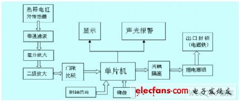
Figure 1 system overall module diagram
2.1.1 Single Chip Microcomputer
As a kind of CPU which is often used in the control system, the single chip has the characteristics of low price, simple programming and stable operation, so it has a broad market space. This design uses AT89S52, which is responsible for collecting the signal from the detection unit and the time read from the clock chip. According to the working mode set by the user, the corresponding sound and light alarm circuit, the outlet blocking circuit, the counting circuit and the voice playing circuit are activated. At the same time, the output control of the display module is completed.
2.1.2 Signal Detection Section
(1) Core detector - pyroelectric infrared sensor According to scientists, any object whose temperature is higher than absolute zero (-273 °C) always radiates infrared rays to the outside, the size of the radiant energy and the temperature of the object and infrared The wavelength of the radiation is related and satisfies λ m &TImes; T= μm &TImes; K ≈ 3000. Detectors using the infrared principle generally operate in three bands of 2 to 2.6 μm, 3 to 5 μm, and 8 to 14 μm.
At present, infrared detection is increasingly used in communications, military, aerospace, medical and other scientific fields.
This design uses RE200B, working voltage 3-10V, mainly detects 8 ~ 14 μ m infrared signal, output 1mV, 0.1 ~ 10Hz (depending on the speed of human body movement) weak sine wave signal. The human body radiates infrared rays of about 10 μm due to the constant body temperature, which is just in the middle region of the detection band, so the sensitivity is high. The two internal thermoelectric elements with the same characteristics are connected in series or connected into a differential balance circuit, which can suppress the interference caused by the temperature change. The introduced N-channel junction field effect transistor is connected in a common leakage form to complete the impedance transformation and convert the charge signal into a voltage signal. as shown in picture 2. Adding a Fresnel lens in front of the sensor, when someone walks in front of the lens, the infrared rays emitted by the human body alternately enter the "high-sensitivity zone" from the "blind zone", so that the received infrared signal is pulsed with strong and weak Form input effectively increases the detection range.
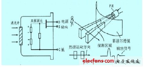
Figure 2 RE200B internal structure and Fresnel lens diagram
(2) Bandpass filter
Since the useful signal output by the detector is concentrated in the range of 0.1 to 10 Hz, it is necessary to design a filter to intercept the pulse signal in the frequency range and filter out the out-of-band noise to reduce the false alarm rate of the system. In this design, an RC low-pass filter and a high-pass filter are used to form a first-order band-pass filter of 0.16 to 16 Hz. The circuit design is shown in Fig. 3. Among them, R10 and C3 form a low-pass filter, and C 1 and R 1 1 form a high-pass filter. According to the formula 12fpRC=, the upper and lower limits of the bandpass filter are fL=0.16Hz, fH=16Hz.
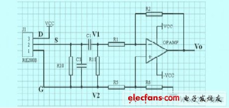
Figure 3 0.16 ~ 16Hz bandpass filter and differential amplifier circuit
(3) Differential amplification
Although the out-of-band noise can be suppressed by the above-mentioned band-pass filter, the pulse signal output by the sensor is only 1 mV, and in the useful signal (differential mode signal), the common mode signal interference which is much larger than the useful signal is inevitably mixed. The useful signal is submerged. If these signals are not further removed, they are directly amplified and sent to the MCU for judgment. When the differential mode signal is amplified, the common mode interference is also amplified synchronously, which cannot be distinguished. Therefore, it is necessary to first suppress the common mode signal and amplify the differential mode signal through the differential circuit to ensure correct detection of the subsequent circuit. The system consists of the inexpensive LM324, as shown by the dashed box in Figure 3. According to the superposition theorem, it is not difficult to obtain. When R 1= R 5 and R 2=R 6 , the output of the differential amplifier is:
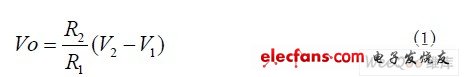
In the above formula, Vo is only related to the signal difference of the input terminal and R2/R1. The amplification factor depends on the value of R2/R1. In this system, the first stage is amplified by 20 times.
(4) Secondary amplification
In the first stage, the common mode signal is mainly suppressed, so it is impossible to have a large amplification factor. In this system, the amplifier needs to be converted from 1 m V to 4 V, and needs to be amplified by 4000 times. In the first stage, it has been enlarged by 20 times, and this level needs to be enlarged by 200 times, which is determined by the value of R4/R3. The circuit is shown in Figure 4.
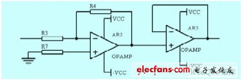
Figure 4 secondary amplification and impedance conversion circuit
Among them, the first stage op amp achieves 200 times amplification, and the second stage is voltage follower to realize impedance transformation.
(5) Threshold comparison
When the human body walks in front of the sensor, it will output a pulse signal with strong and weak changes according to the angle with the sensor. Therefore, it is necessary to set a threshold value, and when the signal is greater than the threshold value, a pulse signal is output. The system uses a double threshold circuit, as shown in Figure 5. The upper and lower thresholds are set to 3.75V and 1.25V, respectively. Two diodes provide a stable output.
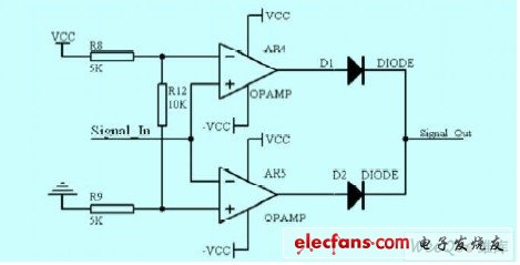
Figure 5 threshold comparator
2.1.3 Clock and keyboard section
This design uses the D130AS low-power real-time clock chip DS1302 to provide the current time. It can time the year, month, day, week, hour, minute and second, and has several functions such as leap year compensation. Two power supplies can be used to realize that the power-down data is not lost. It is connected to the microcontroller using the SPI bus.
When the user selects the working mode, the system completes the real-time monitoring and alarm function with the help of the clock chip.
2.1.4 Display and Alarm Section
The display circuit has two functions: when applied to the "field" work mode, the total number of people in the venue is displayed; when working in other modes, the current time is displayed to determine whether the off-hours are reached, and whether the anti-theft alarm device is activated. This design uses LED display digital visually eye-catching, and it communicates with the microcontroller through the driver 74LS245.
The alarm circuit also has two functions: when working in the "shopping" mode and during business hours, play "Hello, welcome!"; when working in "home" mode or other mode, the time reaches the user set time, A voice alarm is issued and a flashing signal is sent through a special LED to alert the criminal and remind the owner. This design is implemented using the ISD4004 voice chip and power amplifier circuit.
2.1.5 Export Blocking Section
After the above analysis, when an abnormal situation occurs, if only the sound and light alarm is issued, once the owner is not at home, the property cannot be guaranteed, and measures must be taken to prevent the criminals from escaping. An outlet blocking device is added to the design, which is composed of an optocoupler TLP521, a relay group and an electromagnet device. Once the MCU receives the abnormal signal, it sends a command to the relay group through the optocoupler, and the relay group turns on to turn on the electromagnet device to block each outlet.
2.2 Detailed description of various modes of the system
1) "Shopping mall" working mode. If during business hours, play “Hello, welcomeâ€; if it is not within the business hours, activate the sound and light alarm and export blocking circuit to prevent theft.
2) "Venue" working mode. If it is during working hours, the number of people entering and leaving is counted and displayed. If the upper limit of the number of people is exceeded, an audible and visual alarm signal is issued; if not, the burglar alarm signal is issued and the exit is locked.
3) "Family" work mode. This mode is divided into manual and automatic modes. In the manual mode, when the user goes out, press the start button to start the anti-theft alarm mode. Before the stop button is pressed, anyone entering will start the anti-theft alarm; the automatic mode is determined by the MCU according to the time read from the time chip. , Start the anti-theft alarm in a certain period of time, stop the alarm in other time periods, and the time period can be set by itself.
4) "Automatic" mode is the same as the automatic mode in "Home" mode
Base site lead-acid battery protector system is the smart resonance pulse technique for 6V/36V cell battery or 6V/36V battery pack in series with 3PCS 2V/12V cells. It is working as a new generation of high-tech products for daily battery maintenance in telecom base site or electrical power system.
It utilizes the energy from battery self-power or floating power supply, to produce a unique smart electronic pulse, then feed back to the battery through the output line, Resonance with coarse and hard lead sulfated crystals in negative plates of batteries and converted to active substance under the reaction of pulse charging current which dissolve lead sulfated crystals, Keeping the battery working at a high efficiency. Under the disturbance by the smart resonance pulse, the new lead sulfate crystal is prevented from being formed, and the service lifespan of the lead-acid battery is prolonged 1~2 times than before.
There will be individual differences in State-Of-Capacity (SOC) and internal resistance (IR Value) of batteries after used for a certain number of years. It is called the battery unbalancing. Due to the total floating charge voltage of the rectifier remains unchanged and keeps constant, when the battery pack is in floating charging status, the floating voltage of the cells with larger internal resistance will be higher than that of the normal battery, resulting in the normal battery's floating voltage is lower. Batteries floating charged in this unbalancing way for a long time will cause the higher voltage cells seriously water dehydrated, and the lower voltage cell is in a state of under charged. This way of vicious spiral formed will accelerate the base site batteries premature failure.
Our protector system set a equalized charging function. If the terminal floating voltage of the battery system is higher than the standard value of protector system designed, the system automatically and smartly switches to the over-voltage balanced working state. When the voltage drops lower than standard value, it automatically changes to smart pulse maintaining state. The decrease of battery internal resistance and the improvement of the battery equalization lead to the battery lifespan prolonged.
Base Site Battery Protector System
Base Site Battery Protector System,Stationary Battery Protector System,Online Battery Smart Protector System,Telecom Base Site Battery Protect System
Shenzhen Daceen Technology Co., Ltd. , https://www.daceen-sz.com