1 Introduction
In the manufacturing and use of electronic instruments and meters, there are a large number of printed circuit boards that need to be debugged, measured and repaired, and the values ​​of the resistors and capacitors need to be tested.
This paper introduces a design scheme of digital display resistance and capacitance measurement system based on AT89C51 single chip microcomputer and 555 timer, and then produces the circuit physical object to realize the function of the system. The system uses the 555 timer and the resistance to be tested (or capacitor) to form a multivibrator. The period of the 555 output signal is measured by the MCU timer, and the resistance (or capacitance) is calculated according to the mathematical relationship between the period and the resistance (or capacitance) to be tested. ) value, and then display it through the 1602 liquid crystal display. The simulation results show that the measurement system has the advantages of simple structure, convenience and practicality.
2. Design scheme and principle
2.1 Design Master Plan
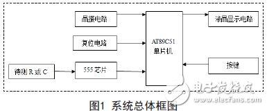
The whole measurement system consists of several circuit modules such as the minimum system of the single-chip microcomputer, the multi-vibrator composed of buttons, resistors, capacitors and 555, and liquid crystal display. As shown in Figure 1.
2.2 Multivibrator principle
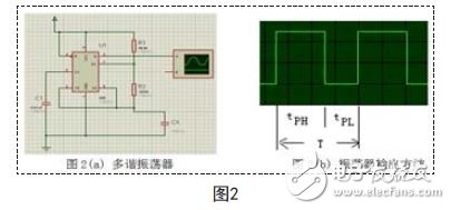
As shown in Figure 2, when measuring the capacitance, the multi-vibrator is composed of 555 and the capacitor CX to be tested and the resistors R1 and R2 (R1 and R2 are known resistors), so that the output terminal Q of 555 will output a periodicity. Wave, connected to the oscilloscope, as shown in Figure 2 (b). This signal is not a square wave with a 50% duty cycle. According to Reference 2, the high time duration in one cycle T is:
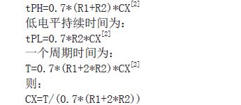
When measuring the resistance, another 555 is used to form a multivibrator circuit, and the resistor RX to be tested is connected to the position of R1 (or RX and a known resistor are connected in series), and CX is replaced with a known capacitor C. The cycle time is:
![]()

2.3 The principle of single chip timing
The periodic square wave signal outputted by 555 is sent to the single chip microcomputer for timing, and a cycle time T of the signal is measured, and then the above mathematical relationship is used for calculation processing to obtain the capacitance or resistance value to be tested. The principle of the MCU timing is to use the external interrupt 0 of the MCU and the output signal of the timer 0.555 to be connected to the external interrupt 0 pin P3.2 of the MCU, and set it to the falling edge trigger. When the output signal of 555 is the falling edge, the external interrupt is triggered, and the timer 0 of the MCU is started to start timing until the next falling edge arrives, that is, one cycle arrives and stops counting. At this time, the timer records a cycle. Length of time.
3. Hardware module design
3.1 MCU minimum system
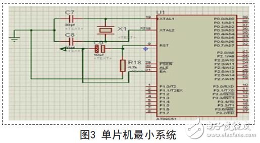
The controller of the system core adopts the AT89C51 single-chip microcomputer. Figure 3 shows the minimum system of the single-chip microcomputer, including the crystal oscillator circuit and reset circuit required for the normal operation of the single-chip microcomputer and the single-chip microcomputer. In Proteus, the default MCU power supply and ground are connected, so the figure is omitted.
- Eye protection
- Suitable for study room and office.
- Modern fashion design.
- Nice clean light from the LED Lamp, won't make your eyes tired while you are reading.
- Stable and natural light structure, no dazzle, glare and stroboflash.
- Dimmable with aluminum heat dissipation profile.
- Low power consumption.
- Flexible arms let you position the Light where you want it.
Rotatable And Foldable Desk Lamp
Foldable Desk Lamp,Rotatable Desk Lamp,Rotatable LED Desk Lamps,Foldable Reading Table Lamp
Shenzhen Superlight Technology Co., Ltd. , https://www.superlighttech.com