Field-Oriented Control (FOC), also known as vector control, is a method used to control three-phase AC motors by manipulating the frequency and voltage output of an inverter. This technique allows for precise control over both the magnetic field and torque of the motor, much like how DC motors are controlled. The term "vector control" comes from the fact that the three-phase current and voltage are represented as vectors during processing.
The concept of vector control was introduced in the late 1960s and early 1970s by K. Hasse from Darmstadt University of Technology and F. Blaschke from Siemens. Hasse proposed indirect vector control, while Blaschke developed direct vector control. Later, Leonhard from Braunschweig University of Technology further refined the idea, making it possible for AC motor drives to gradually replace DC motor drives.
At that time, microprocessors were not yet commercially available, but basic AC motor drivers had already been developed. Compared to DC drives, AC systems were more expensive, complex, and harder to maintain. Additionally, vector control required many components such as sensors and amplifiers, which made it difficult to implement at the time.
One of the key mathematical tools used in vector control is the Park transform, introduced by Robert Park in his 1929 paper. This transformation plays a vital role in analyzing and controlling synchronous and induction motors. It allows the motor’s differential equations to be converted from variable-coefficient to constant-coefficient, simplifying the control process. The Park transform is considered one of the most important papers in power electronics history.
Vector control can be applied to both AC induction motors and brushless DC motors. Initially developed for high-performance applications, it enables operation across the entire frequency range, provides full torque at zero speed, and supports fast acceleration and deceleration. Compared to DC motors, AC motors are smaller, cheaper, and more energy-efficient, making them increasingly attractive for industrial use. Beyond industrial applications, vector control is also found in some household appliances.
In the VFD-VE series, the core technology is FOC (Field Oriented Control), often referred to as magnetic field-oriented or vector control. More and more motor drivers are adopting this method because it ensures the motor operates at peak torque continuously, leading to higher efficiency, better dynamic response, precise speed control, and reduced torque ripple. It also ensures smooth and stable motor operation during startup, running, and shutdown.
**The origin of vector control**
To understand vector control, consider how a current-carrying wire experiences force in a magnetic field, following the left-hand rule. In a permanent magnet synchronous motor (PMSM), the rotor contains permanent magnets, and the stator has multiple windings. FOC works by combining the stator currents into an equivalent current vector that rotates at the same angular velocity as the input power source.
This current vector is then transformed into a two-axis rotating coordinate system using coordinate conversion techniques. If the coordinate system rotates at the same angular velocity as the motor, the current vector appears stationary, effectively behaving like a DC signal. This allows the motor's torque to be directly proportional to the current, provided the rotor flux aligns with the d-axis and the d-axis current remains constant.
Once these conditions are met, the motor’s torque becomes proportional to the stator current, enabling control similar to that of a DC motor. This makes FOC a powerful and precise method for motor control.
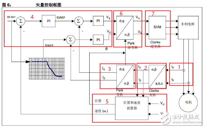
**Working principle diagram**

1. Collect two-phase current signals
2. Apply the Clarke transform to obtain two orthogonal currents
3. Use the Park transform to convert the currents into Id and Iq components. Iq relates to torque, while Id relates to flux. Typically, Id is set to zero in practice. These values are now DC-like and can be controlled independently.
4. Send Id and Iq to PI controllers to generate Vd and Vq outputs
5. Determine the motor’s position using a sensor
6. Perform the inverse Park transform to get the biaxial voltages
7. Apply the inverse Clarke transform to Va and Vb to obtain the three-phase voltage required to drive the motor via the inverter bridge.
Three Phase Ammeter,Voltage Ammeter,Three-Phase Power Meter,Power Instrument
zhejiangjinyidianqiyouxiangongsi , https://www.jooeei.com