First, the power analyzer definition
The power analyzer is a multi-function instrument that integrates waveform display, harmonic analysis, flicker analysis, integration, and more, in addition to accurate measurement of voltage, current, and power, as shown in the following figure.

Figure 1 Power Analyzer Features
The basic function of the power analyzer is a multi-channel high-precision power measuring instrument that can accurately measure multi-phase high voltage and large current, calculate active power P, reactive power Q, apparent power S, power factor, phase, energy. Cumulative parameters, usually used to test the efficiency and power consumption of power converters such as inverters, inverters, motors and transformers. The following figure shows an application example of a power analyzer in a frequency converter and a motor drive system.

Figure 2 Inverter, motor drive system power analysis and detection
With the rapid development of energy saving and new energy fields, power analyzers are widely used in electric vehicles, electrified high-speed railways, solar photovoltaic inverter power generation, wind power generation, motors, transformers, fuel cells, electronic ballasts, energy-saving lamps, Development and performance evaluation of power supplies for switching power supplies, uninterruptible power systems (UPS), power tools, information and office equipment (printers, scanners), and home appliances. It is also suitable for monitoring and analyzing the operation quality of power grids, providing harmonic analysis and power quality analysis in power operation.
Second, the composition of the power analyzer

Figure 3 composition of the power analyzer
As shown in Figure 3, determined by the function of the power analyzer, on the one hand, the power analyzer needs to complete the measurement of the external input signal, including the voltage and current signals of the device under test, and the signal of the torque/speed sensor; on the other hand, The measured data is calculated to obtain parameters such as voltage, current, power, efficiency, etc., and the input signal can be processed and analyzed, for example, harmonic analysis, FFT analysis, waveform viewing, etc., and data interaction with external devices can be performed. .

Figure 4 System design of power analyzer
It can be determined by the functional requirements of the power analyzer. The system structure of the power analyzer, as shown in Figure 4, is mainly composed of the acquisition board and the main board. The acquisition board realizes the acquisition of single-phase input, including a voltage channel and a current channel. The motherboard mainly implements display and communication functions.
Third, the realization of the power analyzer
The core function of the power analyzer is to accurately collect the input signal, and the absolute synchronization must be ensured between each channel. Therefore, the focus of the power analyzer is to ensure the synchronization of the acquisition part and the high precision and stability of the sampling. .
3.1 Low-temperature drift, low noise high-speed data acquisition
The power analyzer's target accuracy is as high as 0.02%. The two most difficult problems for high-precision measurement are temperature drift and noise. The block diagram of the entire analog front end is shown in Figure 5, where the temperature drift and noise of each link will affect the final measurement accuracy.

Figure 5 analog front end block diagram
If you want to ensure the measurement accuracy, this must ensure that the temperature drift and noise of each link is very low, or the compensation process between each link can be realized.
For the temperature drift problem, the first temperature drift is inevitable. All analog devices have a temperature coefficient. The parameters will change with the temperature drift. At the same time, because we can't guarantee that the instrument works in a constant temperature environment, all must consider the temperature drift. problem. Solving the problem of temperature drift First, the component selection must consider the selection of some devices with small temperature drift. The circuit design considers the temperature drift compensation, adding the compensation circuit to reduce the temperature drift, avoiding the saturation problem of the related amplifier circuit, and then designing Self-calibration circuit, real-time calibration of the temperature drift of each link during measurement, minimize the influence of bias drift, then component matching and layout problems, process gain compensation circuit, minimize the effect of gain error, and simultaneously ADC The conversion reference voltage and the analog front-end conditioning reference voltage use the same set of voltages to account for the effects of reference voltage drift, and a 16-bit resolution ADC for high-speed acquisition.
For the noise problem, the internal noise of the circuit and the external noise should be considered. The processing of the internal noise needs to consider the problem of the principle design. The external noise problem needs to consider the layout and shielding of the circuit board. In the circuit design, it is necessary to consider the problem of handling thermal noise and op amp noise, and the circuit layout needs to consider special treatment for the parts that are susceptible to interference. Then design a reasonable filter to filter out some noise. In addition, the design of the shield case must be considered to reduce external noise interference.
3.2 High precision synchronous sampling
The biggest difference between a power analyzer and an oscilloscope and a multimeter is that it can simultaneously analyze voltage and current signals to achieve analysis of the power signal. If accurate analysis of power is to be achieved, the voltage and current signals must be accurately measured, and both must be implemented simultaneously. Sampling of voltage and current signals, voltage and current signals must occur at the same time in each digit of the ADC digitization process, otherwise synchronous measurements cannot be achieved. In order to achieve strict synchronous measurement, the industry's highest synchronous clock and 100MHz synchronous clock with high stability temperature compensation are adopted inside the power analyzer to avoid the error introduced by the clock drift caused by temperature variation, and the ADC is strictly guaranteed for each channel. Simultaneous measurement of voltage and current ensures the accuracy of power measurement.
The maximum error caused by the 100MHz synchronous clock is 10ns, and the cycle is 20ms for the 50Hz power frequency signal, so the phase measurement error caused by the 10ns clock error is

If the sync clock is 10MHz, the phase angle error will be 0.0018°.
For the sake of discussion, it is assumed that the measured voltage and current are standard sinusoidal signals, then the power operation formula is
![]()
Where φ is the phase angle error caused by the out-of-synchronization, so it can be seen that the accuracy of the power measurement is directly affected by the phase angle.
When the phase angle of voltage and current is small, that is, when the power factor is large, the phase error of 0.0.018° has little effect on the measurement accuracy, but the power error caused by the phase error of 0.00018° in the case of extremely low power factor is It is obvious that the error comparison is shown in the following table. If the synchronous clock frequency is reduced, the measurement error will be multiplied, which is the main reason why the current power measurement equipment cannot achieve accurate measurement under extremely low power factor.

Table 1 Measurement error caused by 100MHz synchronous clock
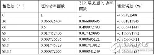
Table 2 Measurement error caused by 10MHz synchronous clock
From the above table, we can see that the 100MHz synchronous clock used effectively guarantees the measurement accuracy under extremely low power factor. When the power factor is lower than 0.01, the power measurement accuracy is better than 0.6%.
3.3 High common mode rejection
The biggest difference between a power analyzer and an ordinary power measurement instrument is that it is necessary to measure multiple voltage and current signals at the same time, and each measurement channel must be isolated and floating, and the isolation withstand voltage reaches several kilovolts or more. The block diagram of the acquisition board is shown below. The isolation withstand voltage reaches 5kV. Due to the strict isolation, it can well meet various wiring applications and ensure the safety of wiring and users.

The analog front-end floating ground can provide good isolation and safety effects, but due to the existence of the floating ground, the common-mode voltage Vc between the shielded shell of the analog front end and the ground of the casing is as shown in the following figure. The measured voltage Vd, the shield case and the analog front end are connected together. Since the measured signal Vd is floating, there is a common mode voltage of Vc between Vd and the ground. Since the analog front end floats, the common mode voltage Vc is added. The stray capacitance Cs between the shield case and the case, so the value of Cs directly affects the magnitude of the common mode current Ic, Ic flows through the negative end of the signal under test, and the common mode current is applied to the negative input impedance. The common mode current is converted into a differential mode current, which causes interference to the signal under test, resulting in inaccurate measurement. Therefore, the value of the common mode voltage Vc should be reduced as much as possible in practical applications. The instrument design should minimize the spur of Cs. The value of the capacitor.

The stray capacitance Cs of the power analyzer is less than 60pF, so the common mode impedance of the 50Hz signal is 53MΩ, assuming the negative end resistance is 1Ω, so the theoretical error is 0.018ppm, the theoretical common mode rejection is up to 159dB, and the actual measured power analysis The common mode rejection of the instrument is greater than 120dB. The significance of 120dB is that when there is 1000V common mode interference, our measurement results only have 1mV error, ie the common mode interference is less than 1ppm.
Four: innovative system architecture

Figure 6 internal PCIe-based high-speed transmission architecture
Traditional power analyzer products have a relatively early design process and weak processing power. There is no way to balance the performance and fast storage performance.
In the design of power analyzer products, we adopted an innovative PCIe architecture, which greatly improved the internal data interaction speed of the power analyzer and solved the bottleneck of large-scale data storage and processing. The following table shows the types of buses commonly used inside the instrument. From the data in the table, the bandwidth and processing capacity of the PCIe bus is much higher than that of other types of bus interfaces, and the transmission speed is as high as 2.5 Gb/s.

Table 3 common bus bandwidth comparison
Using the PCIe architecture, the power analyzer designed this time is the industry's only power analysis instrument that supports 10ms update rate. The 10ms update rate is a revolutionary breakthrough in the history of power analyzers while meeting the needs of power measurement and data logging. Because in traditional tests, if you want to see faster measurements, if you want to see full-wave analysis or half-wave analysis, you can only spend a lot of money and time to buy and learn another instrument - Recorder, but in the end you will find that your problem is still not solved very well, you can not view the measurement results in real time, you can only go into a vicious debugging mode of record-software analysis-debugging-recording-software analysis, wasting a lot of Time and money, the analysis process is extremely painful. Supporting the 10ms update rate The birth of the power analyzer will completely liberate the user from this strange circle of debugging, real-time update and processing capabilities, so that every modification during debugging will be immediate, so that you can quickly see the results.
Led Emergency Light have been divided into two heads emergency lights , bulkhead emergency lights , emergency ceiling lights and emergency bulbs . The role of emergency lights is an emergency state evacuating people , generally used in public places . All emergency lights use LED source , its advantages are high brightness , low power consumption , LED lighting effect than the traditional light source energy saving nearly 80% .

Led Emergency Light,Rechargeable Emergency Lighting,Recessed Emergency Light,Automatic Emergency Light
Jiangmen City Pengjiang District Qihui Lighting Electrical Appliances Co., Ltd , https://www.qihuilights.com