0 Preface
The car headlight system is mainly used for road lighting at night or in harsh environments. Night traffic accounts for 25% of total traffic, while night traffic accidents account for 47% of total traffic accidents. There are many reasons for night traffic accidents. The decline of headlight performance is one of the main reasons. . Traditional headlamp sources are incandescent, halogen and High Intensity Discharge Lamps (HID). Incandescent and halogen lamps typically last only a few hundred hours, and HIDs have a lifespan of only a few thousand hours. Therefore, the search for a new and durable light source to replace the traditional light source has a positive effect on improving the performance of the headlamp and reducing the occurrence of night traffic accidents.
Light Emitting Diode (LED) is a new solid light source that is competitive in the 21st century. Compared with traditional light sources, it has the advantages of long life, small size, low energy consumption, reliable and durable, fast response, flexible design and flexible control. LED has been widely used in interior lighting devices and exterior signal devices. With the development of white LED technology, the luminous flux of single-chip LEDs will continue to increase. It has become an inevitable trend that LEDs replace traditional light sources for headlamps. At the same time, due to the flexible design and control of LEDs, the adaptive headlight system with LED as the light source can realize the adaptive function of the beam more effectively.
At present, the main factors limiting the application of LEDs to automotive headlight systems are: the efficacy and luminous flux of a single LED, and the efficacy of the system. The efficacy and luminous flux of a single LED determines the number of LEDs used in the LED headlamps, which in turn determines the structure and heat treatment of the LED headlamps. The luminous efficacy of a headlamp is defined as the proportion of the luminous flux that is emitted to the ground by the luminous flux per unit lumen emitted by the light source. The higher the luminous efficacy, the smaller the number of LEDs used in the headlamp.
In view of the main problems faced by LED headlamps, this paper proposes a light distribution design scheme of LED front-illumination low beam lamp based on GB4599-94, and then approaches the light distribution scheme through a design example to verify qualitatively and quantitatively. The feasibility of the light distribution scheme provides a favorable guide for the design of the LED car headlight system in the future.
1 GB4599-94 headlamp low beam light distribution standard
The headlight low beam lamp is a kind of lighting lamp that is used at low speed or at the time of the car. It should be used not only to ensure that the driver can see the obstacles 40m in front of the car, but also to make the oncoming driver or pedestrian dazzle. . GB4599-94 requires a low-beam headlight with a clear cut-off line to meet the above-mentioned low beam illumination requirements. The headlamp light distribution screen is shown in Figure 1. The test points and tests on the light distribution screen. The illuminance requirements for the area are shown in Table 1.
Table 1 Light distribution requirements for the low beam of the headlights (unit: lx)


Figure 1 headlight light distribution screen
2 LED low beam light distribution design
The light distribution of LED front-illumination low beam light is GB4599-94, which adopts computer-aided design method. The light distribution process is shown in Figure 2.
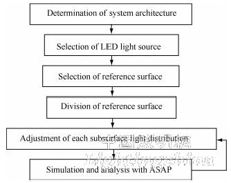
Figure 2 LED low beam light distribution process
2.1 System Type Determination
The efficacy of LED headlamps depends on the type of optical system used for the headlamps. LED headlamps should use optical systems with higher efficiency of light energy transmission. The LED headlamp optical system can be reflective, refractive, total internal reflection (TIR) ​​and composite. Among them, the reflective front illumination system has high efficiency and mature design technology. According to the article, the LED headlamp adopts a reflective structure.
2.2 Light source selection
Unlike conventional light sources, the general LED light is relatively concentrated. When the current lamp adopts a reflective structure, the maximum light intensity of the selected LED should not be concentrated near the optical axis, considering the large illumination range requirements of the headlamp and the effective use of the LED light. The normal light intensity of the side-emitting LED is often small, and the angle corresponding to the maximum light intensity is generally 75° to 85°, so the side-emitting LED is an ideal light source for the reflective LED headlamp. When selecting a specific side-emitting LED, the luminous flux of the LED and its luminous efficiency should be considered comprehensively.
2.3 Basic surface selection
When designing a low beam reflector, a paraboloid is generally used as the base surface. The paraboloid can be obtained by rotating a parabola around its principal axis. The parabolic equation can be expressed as

Where f is the focal length of the parabola, 狉 is the radial angle of the parabola focus to the point on the parabola, and θ is the corresponding half aperture angle, as shown in Figure 3.

Figure 3 Rotating paraboloid
Considering the limited size of the position of the lamp on the car body, the diameter of the light exit hole should be selected to meet the requirements of the body size of the lamp, and the reflector should collect as much LED light as possible. Therefore, the minimum half-angle angle of the parabola can be determined according to the light intensity distribution of the LED, and then the focal length of the parabola is determined according to the external dimensions of the lamp to determine the base paraboloid.
2.4 Basic plane division and sub-surface light adjustment
ReflectorCAD is a light distribution software designed specifically for headlight reflectors. According to the selected light source, the light source model suitable for ReflectorCAD is established, then the basic parabolic model is established in ReflectorCAD, and the light source model and the paraboloid model are placed reasonably, and then the base parabola can be divided.
In Fig. 4, the annular area indicated by the thick solid line is a pattern seen along the optical axis of the base surface and against the direction in which the light is emitted, wherein the small circle corresponds to the mounting hole of the base surface. First, the base surface is divided into two parts: area A and area B according to each test area and the cut-off line on the light distribution screen. The shaded part in the annular area is area A, and the remaining part is area B; after the light source is reflected by area A Irradiation on the area between the light-cut cut-off line and the horizontal line passing the HV point on the light distribution screen, the light source light is reflected by the area B and then irradiated onto the area below the horizontal line of the HV point on the light distribution screen; afterwards, respectively, the area A and Region B performs sub-block partitioning, and the manner of sub-block partitioning is not unique, but the aesthetics of the reflector should be ensured. According to the light distribution requirements of the low beam, the position and curvature of each sub-block are adjusted by reasonably adjusting the illumination distribution of the light source reflected by each sub-block on the light distribution screen, and the light conforming to the regulations is formed by superimposing all the light distributions. type. When adjusting the position and curvature of the sub-block, try to ensure the connection between adjacent sub-blocks.

Figure 4 Basic paraboloid division
2.5 ASAP simulation analysis
GB4599-94 has strict requirements on the illumination of each test point and test area. The light distribution map obtained by ReflectorCAD is only a rough light distribution, and detailed simulation analysis is also needed by ASAP.
In ASAP, the illumination of each test point and test area is analyzed in detail according to the light distribution requirements of the headlamp low beam. When the simulation results do not meet the light distribution requirements, ReflectorCAD should be used to adjust the light distribution map accordingly, and then import into the ASAP analysis, and then repeat until the light distribution obtained by the ASAP simulation meets the light distribution requirements of the headlight low beam.