It should be said that after really understanding TS, or after reading the book "Digital TV Business Information and Coding" recommended by friends, MPEG2 TS and digital TV are inseparable, and it is worth summarizing some of these relationships.
This article refers to the address: http://
ISO/IEC-13818-1: System Part; ISO/IEC-13818-2: Video; ISO/IEC-13818-3: Audio; ISO/IEC-13818-4: Conformance Test; ISO/IEC-13818-5 : Software part; ISO/IEC-13818-6: Digital storage media command and control; ISO/IEC-13818-7: Advanced audio coding; ISO/IEC-13818-8: System decoding real-time interface;
The MPEG2 system tasks include: 1. a protocol that specifies data transmission in packets; 2. a protocol that specifies synchronization of data streams at both ends; 3. a multiplexing and demultiplexing protocol that provides multiple data streams; and a protocol that provides data stream encryption. . Storing and transmitting data streams in packets is the main point of the MPEG2 system.
The ES is a stream of data directly from the encoder, which can be a collective name for an encoded video stream, an audio stream, or other encoded stream. After the ES stream passes through the PES packetizer, it is converted into a PES packet. The PES package consists of a header and a payload. The specific format is as follows:
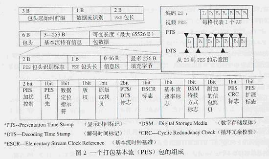
It can be seen that the PTS/DTS is played in the PES package. These two parameters are the key to solving the video and audio synchronization display and preventing the decoder input buffer from overflowing or underflowing. PTS indicates the time at which the display unit appears in the system target decoder (STD), and DTS indicates the time at which all bytes of the access unit are removed from the STD's ES decoding buffer. The header of each I, P, B frame has a PTS and DTS, but the PTS and DTS are the same for the B frame, and there is no need to mark the DTS of the B frame. For I frame and P frame, it must be stored in the reordering buffer of the video decoder before display. After delay (reordering) and then display, it must be marked PTS and DTS respectively.
The ES first needs to be packaged into a PES stream packet, and then the PES is packaged into a PS or TS packet for storage or transmission as needed. Each ES only contains the encoded data stream of one source, so each PES only contains the data stream of the corresponding source.
For PS streams, each PES packet header contains PTS and DTS, stream identification codes, used to distinguish ESs of different natures. The PES packets are then multiplexed into PS packets by a PS multiplexer. In fact, the PES packet is broken down into smaller PS packets. At the time of decoding, the demultiplexer decomposes the PS into individual PES packets, and the unpacker then splits the PES packet into an ES of video and audio, and finally inputs it to the respective decoder for decoding. One question is: How do you ensure the synchronization of video and audio when each ES is decoding? In addition to the cooperation between PTS and DTS, an important parameter is SCR (system clock reference). At the time of encoding, PTS, DTS and SCR are generated by STC (system time clock). When decoding, STC will regenerate and use phase-locked loop (PLL-phase lock loop) to use local SCR phase and input. The instantaneous SCR phase lock comparison is to determine if the decoding process is synchronized. If not, the instantaneous SCR is used to adjust the local clock frequency of 27 MHz. Finally, PTS, DTS and SCR work together to solve the problem of synchronous playback of video and audio. The PS format is excerpted as follows:
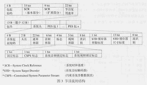
The length of the PS packet is long and variable, and is mainly used in an error-free environment, because the longer the synchronization, the more difficult it is to synchronize, and the more difficult it is to reassemble in the case of packet loss. Therefore, PS is suitable for the editing of program information and the application of local content applications.
The TS stream is also a combination of one or more PESs, they can have the same time base or they can be different. The basic multiplexing idea is that multiple PESs with the same time reference are now used for program multiplexing, and then each PS with independent time reference is used for transmission multiplexing, and finally TS is generated.
The TS packet consists of a packet header and packet data 2 parts, wherein the packet header may also include an extended self-applied zone. The length of the packet header is 4 bytes, and the total area of ​​the self-use area and the packet data is 184 bytes. The length of the entire TS packet is equivalent to 4 ATM packet lengths. The header of the TS packet is represented by the following table: synchronization byte, transmission error indicator, payload unit start indicator, transmission priority, packet identification (PID-Packet Identification), transmission scrambling control, adaptive zone control. And the continuous counter consists of 8 parts.
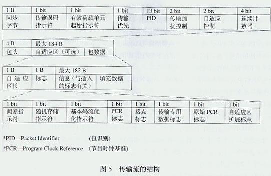
Wherein, the automatic correlation feature of the synchronization byte bit string can be used to detect the packet restriction in the data stream, and the packet synchronization is established; and the transmission error indicator refers to the fact that the error correction decoder can represent 1 bit when the error cannot be eliminated. Error code, but cannot be corrected; the payload unit start indicator indicates whether the data packet has determined start information; the transmission priority is to assign priority to the TS packet; the PID value is determined by the user, and the decoder is based on the PID Differentiate the TS packets from different ESs on the TS to reconstruct the original ES; transmit the scrambling control to indicate whether the data packet content is scrambled, but the packet header and the adaptive region are never scrambled; adaptive region control, 2 bit indicates whether there is an adaptive region, that is, (01) indicates that there is no adaptive region with useful information, (10) indicates that there is no useful information with adaptive region, (11) indicates that there is useful information with adaptive region, (00) Definition; the continuous counter can count the PID packet transmission order. According to the counter reading, the receiving end can judge whether there is packet loss and packet transmission order error. Obviously, the packet header has synchronization, identification, error detection and encryption functions for the TS packet.
The TS packet adaptation area is composed of an adaptive sector length, various flag indicators, information related to the insertion flag, and padding data. The flag part is composed of a discontinuous indicator, a random access indicator, an ES optimization indicator, a PCR flag, a contact flag, a transmission dedicated data flag, an original PCR flag, and an adaptive area extension flag. What is important is the PCR field of the flag portion, which provides synchronization data to the codec's 27MHz clock for synchronization. The process is to determine whether the decoding process is synchronized by using the PLL to compare the local PCR phase with the input instantaneous PCR phase lock during decoding. If not, the instantaneous PCR is used to adjust the clock frequency. Because digital images use complex and different compression coding algorithms, resulting in different data for each image, making it impossible to obtain clock information directly from the beginning of compression-encoded image data. To this end, some (but not all) of the adaptive regions of the TS packets are selected to convey timing information. Thus, the adaptive region of the selected TS packet can be used to determine the control bit of the packet information and important control information. The adaptive zone does not need to be sent with each packet, and the number of transmissions is mainly determined by the transmission-specific time-scale parameters of the selected TS packet. The random access indicator and the contact mark in the flag provide a random entry point for the data stream compressed randomly into the I frame when the program changes, and also facilitate the insertion of the local program. The padding data in the adaptive zone is because the PES packet length cannot be exactly converted to an integer multiple of the TS packet, and the last TS packet retains a small amount of useful capacity, which is filled by padding bytes, thereby preventing the buffer from underflowing and maintaining The total code rate is constant.
The previous three sections summarize the basic format of MPEG2 TS, including PES, PS and TS, and an introduction to related fields. Then, as a transport stream, the TS packs/multiplexes the content, causes its media content to become TS transmission, and finally decodes at the decoding end. In simple terms, TS is a transport layer protocol stack that can carry various content transmissions, such as MPEG, WMV, H264, and even IP. How is the transmission specification defined? This is PSI (program Specific information) Things to do.
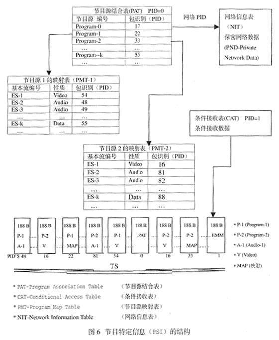
The PSI consists of four tables: PAT, PMT, CAT, and NIT. These four tables describe the transmission structure of all ES streams included in a TS, respectively. The first concept is that the TS is spread in the form of a packet. The codec needs to identify the content carried in the TS stream with a certain packet ID. For example, the PAT table will exist in one or more TS packets, so It is represented by a special package ID. In addition, different ES streams also need different packet IDs to identify them. We have two tables, PAT and PMT. The decoder can distinguish the TS packets from different ESs on the TS according to the PID.
The decoding of TS is performed in two steps. One is to parse the PAT table from the TS packet with PID 0, and then find the PID of each program source from the PAT table. Generally, such program sources are composed of several ES streams. And described in the PMT table, and then through the PID of the program source, you can retrieve the PID of each ES in the PMT table. Second, the decoder distinguishes the packets on the TS stream according to the PID of the ES stream in the PMT table, and decodes the packets according to different ES streams. Therefore, the TS is completed by two layers of program multiplexing and transmission multiplexing, that is, when the program is multiplexed, the PMT is added, and when the transmission is multiplexed, the PAT is added. Similarly, when the program is demultiplexed, the PMT can be obtained, and when the transmission is demultiplexed, the PAT can be obtained. The diagram below is a good overview of its ideas.
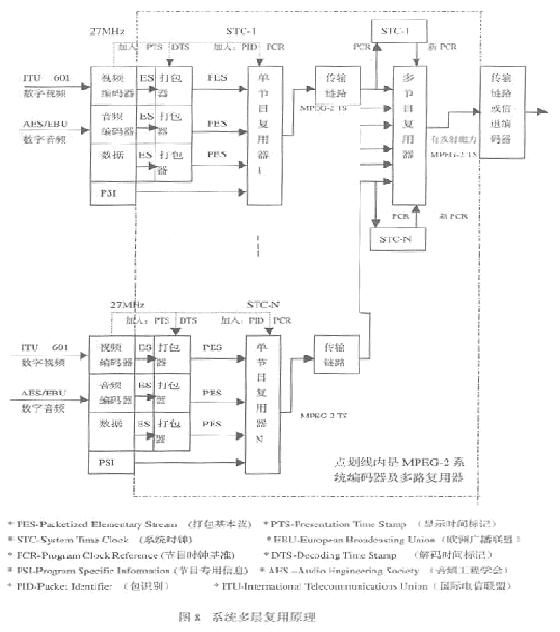
The TS is multiplexed, so it can be used to transmit multiplexed multi-layer programs. In the multiplexing process, it is necessary to pay attention to the time reference and synchronization problems that need to be faced in the decoding process, because demultiplexing requires various information synchronization, so in the multiplexing process, it is necessary to insert relevant Time information: PTS, DTS, PCR.
In the TS formation process, the PTS and the DTS are injected into the PES packet according to the reference of the STC when the ES is packaged into the PES, and then the PID and PCR information are injected into the TS when the PES is cut into the TS. In the packet, when multiple TSs are reused, the PCR of each TS will be extracted, analyzed, and then the new PCR will be generated and injected into the TS according to the unified STC reference. Because the original PAT table information is not applicable, the new PAT table needs to be regenerated and appended to the new TS stream. After this multi-layer multiplexing, the new TS stream can enter the modulation and transmission phase. The process can be seen in the following figure:
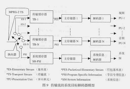
The problem to be faced in the decoding process is: demultiplexing, video and audio synchronization, and no decoding buffer. Demultiplexing separates the programs that TS transmits at different timings in the same channel; video and audio synchronization is coordinated by DTS, PTS and PCR, and PCR is the absolute time scale for reconstructing the system time reference, while DTS and PTS It is the relative time scale of the decoding and reproduction time; the problem of no overflow of the decoding buffer must be realized by means of the system target decoder (STD) model. The basic ideas are as follows:
After the TS stream enters the decoder, the ES flows are first decomposed by the commutator according to a certain timing relationship (including the PSI information stream).
The decomposed ES streams enter their respective transmit buffers, after which their PES streams enter their respective main memories. Note that the PSI traffic enters the system buffer and finally reaches the main memory.
Finally, the decoder extracts media or system information from each main memory according to the DTS information, performs decoding, and performs display processing on the media content according to the PTS information.
The process can be seen in the following figure:
Freestanding Gas Cookers
Enjoy the control and convenience of gas cooking with Freestanding Gas Cookers, featuring four gas burners and 4 brass burner cap to help you create delicious meals for your family and friends.
Key Features
Fuelled by natural gas, Freestanding Cooker is economical and delivers delicious results, letting you enjoy tender, moist roasts with lower running costs.
The spacious cooktop features a triple ring burner for fast, efficient heating, and flame failure protection to cut off the gas flow if the flame is extinguished.
The gas oven offers a range of cooking functions, including electric grill, static gas, and fan assisted gas for even heat distribution.
Crafted with low porosity titanium enamel and a removable glass door, the Cooker is easy to clean.
With a 10 AMP plug already fitted to the Cooker, installation to a standard power outlet is simple and easy.
Black color body
Glass top
Stainless Working Top
4 Gas Burners with 4 brass burner cap
(1 large 2 medium 1 small)
Manual Ignition
Enamel Grill
Knobs with Base
Double Glass Oven Door (mirror)
Downside Oven Burner
1 Pcs Oven Grill
Aluminum Handle
Duck feet
Oven Size:60L
Product Size:50X50X81cm

Freestanding Gas Cookers
Freestanding Gas Cookers,Free Standing Electric Combination Cooker Oven,Large Volume Oven Cooker,Six Burners Glass Cover Cooker
xunda science&technology group co.ltd , https://www.gasstove.be