Foreword: DIY is a way of life, it is a kind of spirit. The satisfaction of giving people in this process is actually more important than the incident itself.
Among the dwellings is a Haier Haier LK47K1 47-inch LCD LCD TV, which has been in service for five years and has been diligent and diligent. Did not think about a night boot, cool flashes of backlighting did not nearly explode my eyes.
Failure performance: normal boot, normal sound and video, backlight flash, 5-6 times per second. Because the strobe is not easy to shoot, here we brains up the white light quickly and easily.
Analysis of the cause of the failure: Since the screen and sound are displayed normally, it means that the motherboard and the screen should be no problem, and the backlight flashes, it will naturally point to the power board and backlight board. That's nothing to say, disassemble it~

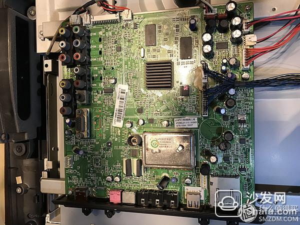
In fact, the structure of LCD TVs is not complicated. The middle board is the power board and the left board. Give the main power board and motherboard a close-up
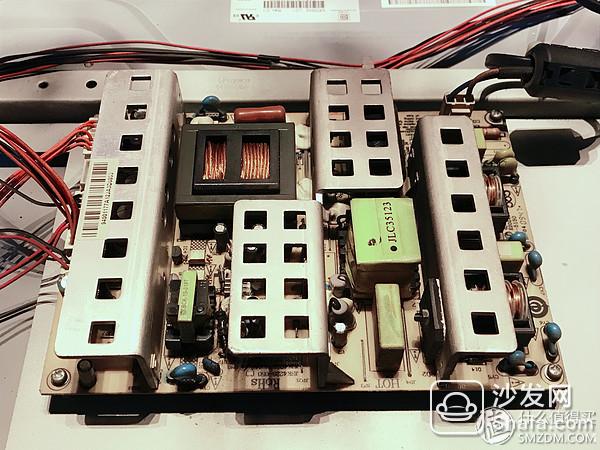
Began to find the specific problem parts, first traversed the large and small electrical components, and found no tragic burst or burned. I thought, is it bad circuit board? That can only replace the entire board? How could you admit so early! Take out the multimeter and take one measurement. First of all, of course, the 24V output from the power board to the screen connection cable. A test, of course, only 22.9V
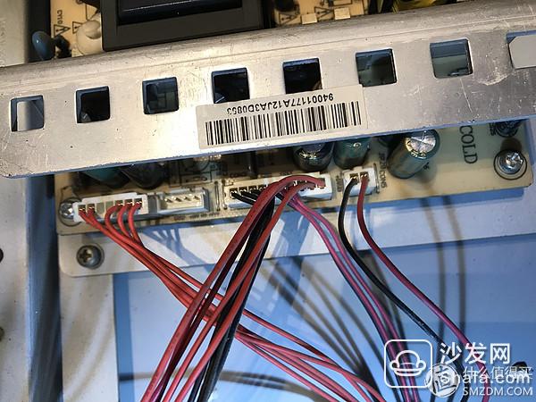
In the middle is the interface to the screen
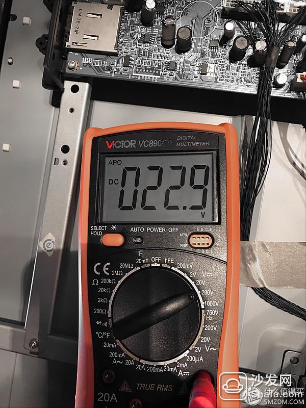
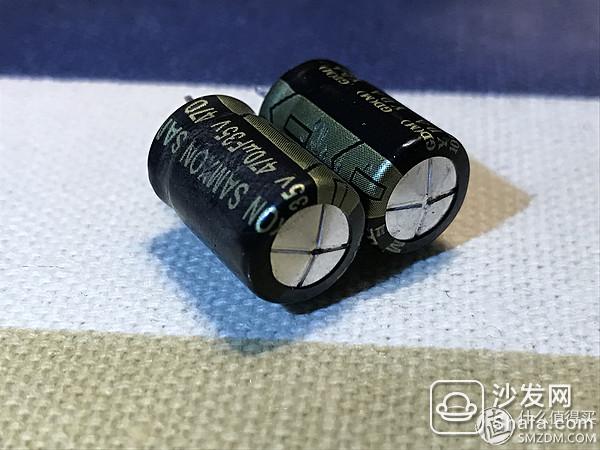
Do not look at this small 1V gap, it should be the cause of the backlight does not flicker. So once again check the power board output circuit, and finally found the fault in the corner culprit - two "pregnant" capacitors! Drum bulging is not obvious, and there are heat sinks blocked, the first actually did not see! Must give it a close-up!

How to do? Take repair? It is obviously not worthwhile to change two capacitors to thirty or forty yuan, but it also violates DIY's own hands-on spirit. Then decided to do it yourself, replace the expansion capacitor. Here's a brief description of how to replace the capacitors. As can be seen from the above figure, the K-type explosion-proof pattern has been cracked. The parameter that needs to record the electric capacity here is 35V 470μf, the purpose that is written down is to buy the electric capacity of the same parameter conveniently.
Buy 5 capacitors from the electronic components market (3 spares, so as not to buy bad or other unexpected situations), prepare tools, remove the circuit board, find the corresponding solder joints, open the solder!

Here I use the right hand holding the soldering iron, the left hand with a tweezers clip the capacitor to be removed, and give a certain pull. Touch the solder joint with a soldering iron tip to melt the solder. Since the capacitor has two welding points, after one end is removed (or one end cannot be extracted), the other end is loosened in the same way, and the bulge capacitor is finally removed by constant adjustment. The specific process also requires everyone to understand the actual situation. There are no photos here, after all, one person repaired.
Note: Because of the high temperature of the soldering iron, it is forbidden to contact the soldering iron for a long time to prevent damage to the circuit board.
If you are skilled, then you can remove the two capacitors in 5 minutes. As usual, give it a close-up
Take out the new capacitor and use scissors to cut the two legs to the same length as the removed bad capacitors, leaving them slightly longer. Because the heat sink on the power board is obstructed, it can only be clamped again with tweezers. It must be noted here that the capacitance is positive and negative. In general, when it is purchased, the short period is negative (or there is a “—†on the housing) and it should correspond to the positive and negative poles on the PCB. I have a slashed shadow on the board to indicate the negative side. Take a photo or write it down before taking the old capacitor.
Here are some basic welding methods. It is mainly divided into five steps:
Prepare welding and prepare solder wire and soldering iron. At this time, the iron head that is particularly emphasized should be kept clean, that is, it can be covered with solder (commonly known as eating tin). Generally, it is heated first, then poke it in the solder paste or rosin, and then evenly stick the spot solder protection.
Heat the weldment and contact the soldering iron with the soldering point. Note that the soldering iron must be first used to heat all parts of the weldment.
Melt the solder. When the weldment is heated to the temperature at which the solder melts, the wire is placed on the solder joint. The solder begins to melt and wet the solder joint.
Remove the solder and remove the solder wire after melting a certain amount of solder.
Remove the soldering iron and remove the soldering iron when the solder completely wets the solder joint. Note that the direction of removing the soldering iron should be approximately 45°.
After switching on, check whether the solder joints have been welded or not, and if there is any problem with other solder joints, there is no problem. At this point the multimeter re-test, perfect recovery to 24.3V, check the screen, the strobe phenomenon disappeared, the old machine again to restore vitality!

Fix the power board and restore all kinds of cable Connectors. At this time, you can easily clean up the dust on various parts. In five years, the dust is really too much. This is not on the map.
Cover and complete repairs. Connect the box, open the rouge that is being chased, look it ~~~

Summary: Many times, the maintenance of household appliances is not so difficult. Find more information, and see how similar failures are handled by others. The current electrical appliances are all bad modules, but it is not a good idea to replace the problematic board. The richest family is the price is not expensive.
Finally, I wish you all a Happy New Year! Late night code is not easy, seek reward!
Over time, battery cables have to be replaced due to corrosion or damage. A bad battery cable can cause intermittent starting issues or lack of power to the vehicle, including arcing or power drains.A battery cable consists of multiple stands of wire encased in synthetic material with different types of battery terminals on each end for a reliable connection. Corrosion is the number one cause of battery cable failure, stopping the flow of electricity.
Battery cable, power cable, battery cable assembly, battery wiring
ETOP WIREHARNESS LIMITED , https://www.oemmoldedcables.com