In PCB design, Design Rule is the key to the success or failure of a PCB design. All the designer's intentions and the functional embodiment of the design are driven and realized through the soul of design rules. Exquisite and meticulous rule definitions can help designers in the work of PCB layout and routing, save engineers a lot of energy and time, help designers achieve excellent design intent, and greatly facilitate the design work.
The entire PCB design needs to comply with the rule definition. Including the most basic electrical rules (spacing, short circuit break), wiring rules (line width, wiring style, via style, fan-out, etc.), plane rules (power ground plane layer connection method, copper connection method); and others Commonly used auxiliary rules such as layout rules, manufacturing rules, high-speed design rules, signal integrity rules and so on. After the design is completed, you can also conduct a rule check Design Rule Check to re-examine your design to see if there are any violations of the rules and make improvements and improvements.
This small trick solves problem 6: How to set different rules for different regions? Introduce the use of Room in Altium Designer to divide into blocks and areas, and then set and apply corresponding rules for this area.
Use Room to set the line width rules in a specific area
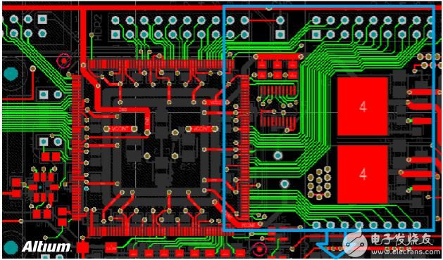
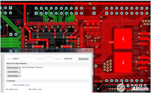
In the definition of PCB rules, for example, if different rules are to be adopted for a specific area, then Room is the first choice to solve such problems. First use Room to frame this specific area and name it Room1. Then select WithinRoom('Room1') in the rule definition, and then you can set various rules for the objects in this Room. For example, as shown in the figure below, the line width rules all violate the minimum line width setting value, so they are all highlighted in green. Then select Room1 for the area on the right, and set a wider line width value of 10mil for it. Then the line width in the Room conforms to the rule definition, and it has been displayed as normal, and there is no green highlight violation. However, in the wires of the same network, the violations are still highlighted in green outside the Room. This is the purpose of the separate rules set by the Room.
After selecting a certain area in the Room, you can not only set the line width rules separately, but also set any rules on the PCB Rule definition page.
Use Room to set the line spacing rules in a specific area
For example, the rules for setting the line spacing of the entire PCB are as follows:
The minimum distance between each network is 10mil
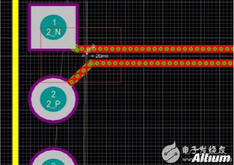
The minimum distance between differential pairs is 20mil
Of course, this is just a setting to show the role of the Room. In fact, when routing, all spacings, including the spacing between differential pairs, are routed in accordance with 10mil. However, in order to create problems, the spacing between the differential pairs is regularly set to 20mil, so that the following error display appears during DRC inspection.
And we accept the 10mil spacing of the differential pair wiring, which is to make the error message disappear. At this time, just use Room to set specific rules for specific objects.
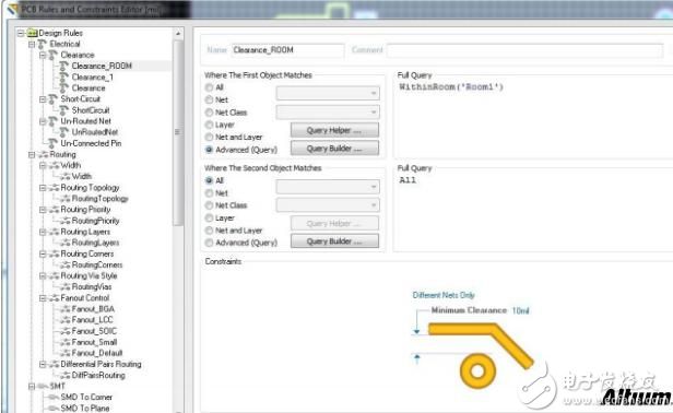
First use the shortcut keys D, M, R, namely Design> Rooms> Place Rectangular Room to create a new Room. And set corresponding rules for it. The term of the object setting rule in Room is withinroom('Room name'). As shown in the figure below, set the electrical spacing in the Room to 10mil.
Then draw a Room, and cover the object (in this case, differential pair wiring) that will use the specific rule.

Obviously, two sets of differential pairs with the same connection and the same spacing, no error is reported for the objects in the room, and the rules set by the new room are used. The objects outside the Room are still reporting errors. This is the effect of Room setting rules for different regions.
Of course, in addition to the above-mentioned Room’s application of setting specific rules for different areas, Room also has two super useful techniques. One is the multiplexing of the layout and routing format used in the multi-channel Room, that is, the Copy Room Format function. The other is to frame a class of components in the Room, so that when you drag these components you only need to drag the Room. You can try these two convenient techniques in your future work.
ZGAR AZ MC Disposable
ZGAR electronic cigarette uses high-tech R&D, food grade disposable pod device and high-quality raw material. All package designs are Original IP. Our designer team is from Hong Kong. We have very high requirements for product quality, flavors taste and packaging design. The E-liquid is imported, materials are food grade, and assembly plant is medical-grade dust-free workshops.
Our products include disposable e-cigarettes, rechargeable e-cigarettes, rechargreable disposable vape pen, and various of flavors of cigarette cartridges. From 600puffs to 5000puffs, ZGAR bar Disposable offer high-tech R&D, E-cigarette improves battery capacity, We offer various of flavors and support customization. And printing designs can be customized. We have our own professional team and competitive quotations for any OEM or ODM works.
We supply OEM rechargeable disposable vape pen,OEM disposable electronic cigarette,ODM disposable vape pen,ODM disposable electronic cigarette,OEM/ODM vape pen e-cigarette,OEM/ODM atomizer device.


ZGAR AZ MC Vape,ZGAR AZ MC Vape disposable electronic cigarette,ZGAR AZ MC vape pen atomizer ,AZ MC E-cig,AZ CC Vape disposable e-cigarette
ZGAR INTERNATIONAL(HK)CO., LIMITED , https://www.oemvape-pen.com