Tag: AI442X PIC
This article refers to the address: http://
Application prospect
With the continuous pursuit of quality of life and the continuous development of residential intelligent technology, the configuration of smart home systems is getting higher and higher, and has more rich content.
The basic functions of smart home include intelligent home appliance control, intelligent lighting, intelligent remote control electric curtains, burglar alarm, access control intercom, fire alarm, gas leak detection, remote meter reading (water, electricity, gas) system, network communication, video on demand, Smart air conditioners, smart water heaters, etc., more and more fresh nouns have gradually become an important part of smart home systems. At present, tens of millions of homes around the world have installed home network products. It is predicted that the demand for home network products will continue to grow substantially in the future. With the rapid and sustained growth of China's economy, the demand for future home networks has also shown a strong growth trend. Among them, smart water heaters, as an integral part of smart homes, have broad market prospects.
The use of water heaters covers a wide range of markets, including homes and hotels. At present, there are mainly electric water heaters, solar water heaters and gas water heaters on the market. In terms of domestic specific conditions, many water heaters now use manual manual adjustment or infrared remote control. The traditional remote control method of household appliances generally uses infrared remote control, but infrared remote control requires no obstacles between the remote control and the body, so it cannot be worn. wall. With the development of technology and the improvement of people's requirements, this function is increasingly unable to meet the requirements of users. To this end, we have developed a water heater with RF wireless remote control and network control, which allows users to control the switch of the water heater at home and in other parts of the office, which greatly facilitates the user and is a breakthrough in the traditional way.
2. Product Features
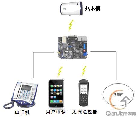
The schematic diagram of the water heater product is shown in Figure 1. The features are as follows:
1 The scheme consists of a network controller, a remote controller, a water heater controller, and a network server. The controllers can independently form multiple independent systems to control the water heater. As shown in Figure 1, the water heater can be arbitrarily selected. control method.
2 Network control The main chip uses Microchip's Internet access application for embedded systems. The 8-bit integrated Ethernet control chip PIC18F66J60 is developed, and the TCP/IP protocol stack based on this chip is embedded in Microchip.
3 wireless remote control chip using the United States Intergration company's IA4421, remote control distance of up to 100 meters, at least can penetrate the 20CM wall for remote control.
4 The network controller and the water heater controller are controlled wirelessly to avoid wiring troubles caused by the installation of the water heater.
3. Network server architecture
The network server is a device that implements communication between devices and external devices in the home network, and is the core component of the home network. Through the devices in the home network, information can be exchanged with the telecommunication network, and information interaction between internal devices can also be performed. The network server establishes a unified data processing center within the home, manages the internal data of the home, and connects to the carrier network externally. It is defined as: a simple, intelligent, standard, and flexible entire home network interface unit that can receive communication signals from different external networks and transmit signals to various devices over the home network. Two main features of a home network server based on a telecommunications network are broadband access capabilities and IP-based data processing capabilities.
The network server developed by our company for smart water heaters is based on network TCP/IP communication, and accesses the water heater through the C/S structure. It integrates database service, SMS service and Web service to provide users with remote control and monitoring functions for the heater. Its simple structure is shown in Figure 2:
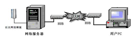
Figure 2 network server architecture
4. Receive control system design
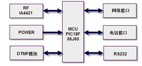
Figure 3 receiving system framework
The main block diagram of the hardware of the receiving control system is shown in Figure 3. This paper only introduces the network interface circuit and wireless circuit part which are more important.
4.1 Network Interface Circuit
The main controller uses PIC18F66J60, which is a new Ethernet microcontroller from Microchip. It has excellent computing performance, rich feature set and competitive price, including a series of serial communication peripherals, up to 2 Independently enhanced USART and two master SSP modules for SPI and I2C? (master and slave) mode operation with embedded Ethernet controller module.
In this paper's connectivity solution, the media access control and physical layer transceiver modules are fully implemented, and the microcontroller can be directly connected to the Ethernet using only two pulse transformers and some passive components. The network interface circuit is shown in Figure 4. The TPIN+/TPIN- and TPOUT+/TPOUT- pins are connected to a 1:1 center-tap pulse transformer for Ethernet operation. When the Ethernet module is enabled, two TPOUT pins will have a continuous current flow; when the transceiver module is transmitting data, a differential voltage will be generated on the Ethernet cable by changing the relative currents of TPOUT+ and TPOUT-. Both the transmit and receive interfaces require the use of two additional resistors and a capacitor to properly connect to the transmission line, minimizing signal reflections and increasing the stability of the communication signal.
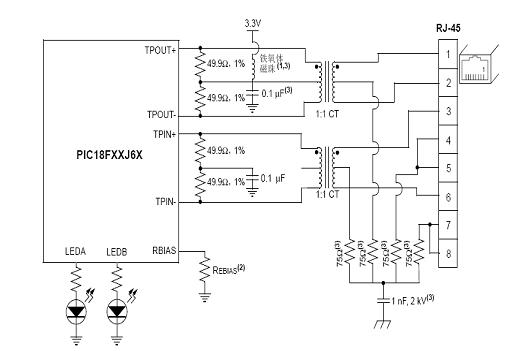
Figure 4 network interface circuit
4.2 wireless interface circuit
The wireless module adopts the wireless transceiver single chip IA4421 of INTEGRATION Company of the United States. The chip is a complete wireless transceiver, including an intrinsic multi-band PLL synthesizer, PA, LNA, mixer, baseband filter, IF amplifier, signal strength indicator RSSI, data quality detection DQD, battery voltage detection, AFC and microcontroller, few external components, stable and reliable performance. The module is a compact, low-power FSK modulation transceiver with high receiver sensitivity and operates in the 433MHz, 868MHz and 915MHz bands with 16 channels per band.
The IA4421 works with only five I/O ports and uses an SPI-compatible control interface as a data communication interface. The functions of each interface are as follows: SCK: SPI serial clock input; SDI: SPI serial data input; NSEL: SPI chip select input (active low); SDO: SPI serial data output; NIRQ: interrupt request output (active low) The chip has the advantages of small size and low power consumption, which is very suitable for wireless devices. The circuit connection is shown in Figure 5.
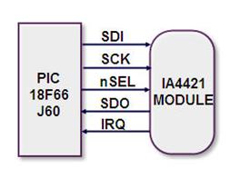
Figure 5 wireless module interface
5. Remote control system hardware framework
The remote control adopts PIC microcontroller and IA4421 wireless transmission chip. The wireless module based on IA4421 operates at 433MHz, the communication rate is 9.6KB, the data transmission distance is not less than 110m, and at least 2 walls can be penetrated. User requirements. The wireless remote controller has the following functions: setting water temperature and temperature, displaying water temperature and temperature, setting instant heating mode, setting host power switch, setting intelligent control, power gear setting, time display, having running mode and sleep mode Wireless learning, when the learning button is pressed, enters the learning state, and the learning indicator LED is on. When the learning is successful, it returns immediately, the LED light is off, and the transparent data transmission state is usually used. The hardware structure of the remote control system is shown in Figure 6.
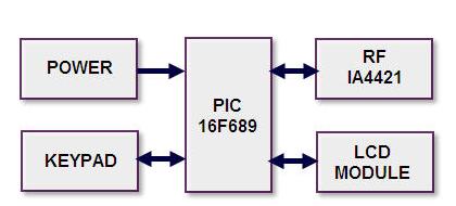
Figure 6 remote control system hardware block diagram
The power section is powered by two 1.5V AAA batteries. When the system is in standby state, the IA4421 and PIC16F689 are in a sleep state, and the LCD is turned off, reducing the power consumption of the system.
The circuit connection of the IA4421 module is basically the same as that of the receiving system. As shown in Figure 4, the SPI is used to communicate with the wireless module.
6. Receive Control System Software Block Diagram
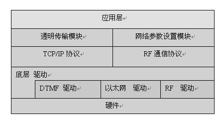
Figure 7 Receive Control System Software Structure
The software design structure of this scheme is shown in Figure 7. Because the process is more complicated and limited by space, this paper only gives a general introduction to its more important parts.
6.1 IA4421 driver process
The RF driver is mainly used to initialize the IA4421 registers, such as communication rate, communication frequency, power management, and output power. The initialization process of the IA4421 is shown in Figure 8. The process is simple and easy for users to understand and use.
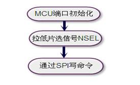
Figure 8 IA4421 driver
6.2 Ethernet driver process
The Ethernet driver has three communication modes, namely TCP SERVER mode, TCP CLIENT mode, and UDP mode. This article uses UDP mode, which is more efficient and faster than TCP mode. In this mode, there is no need to establish a connection request and response, and the data directly performs bidirectional data transmission. The specific process diagram is shown in Figure 9.
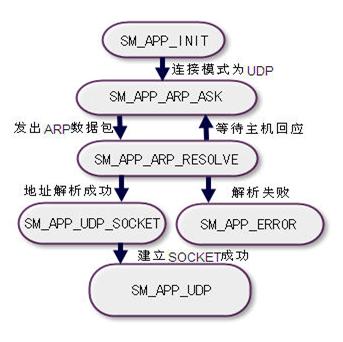
Figure 9 Ethernet driver process
Among them, the status is as follows:
1SM_APP_INIT: Start state, initialized, and enter the relevant state according to the parameter settings.
2SM_APP_ARP_ASK: Issues an address resolution packet to the remote host and requests the corresponding network address according to the IP address.
3SM_APP_ARP_RESOLVE: Accepts the address resolution packet sent by the remote host and sets the network address of the remote host.
4SM_APP_UDP_SOCKET: Establish an UPD connection.
5SM_APP_UDP: Data reception and transmission in UPD connection mode.
6SM_APP_ERROR: Empty status for debugging of the program.
7. RF remote control system software framework

Figure 10 RF remote control software structure
The RF remote control software flow is shown in Figure 10, including MCU initialization, variable initialization, IA4421 initialization, LCD initialization, and loop detection of the main program.
The main loop includes key input detection, wireless data transmission, wireless signal reception and feedback data processing, and LCD data display, that is, the user input information can be correctly transmitted and the various states of the water heater can be fed back to the LCD of the handheld device in time, so that The user can see at a glance.
8. Summary
The solution is mainly based on the intelligent home control solution developed by IAI442X series chip and PIC series microcontroller, which can be easily applied to various smart home systems.
Dmx Cable is customized LED Accessories to meet different led lighing project requirements, we can make Xlr Cable , xlr to xlr able, 3 Pin Dmx Cable, 5 pin DMX Cable. And the length is customized as well. The DMX cable can made by black pvc cable, white pvc cable, black rubber wire, and net wire, even the 18# color wire for indoor dmx signal transfer to get a economic solution.
Photo show of DMX Cable:

DMX Cable
Dmx Cable,Xlr Cable,Xlr To Xlr Cable,3 Pin Dmx Cable
Shenzhen Iseeled Technology Co., Ltd. , https://www.iseeledlight.com