The application of inverter circuits is very extensive. Among the various existing power sources, batteries, dry batteries, solar cells, etc. are all DC power supplies. When these power supplies are required to supply power to the AC load, an inverter circuit is required. In addition, power electronic devices such as inverters for AC motor speed regulation, uninterruptible power supplies, and induction heating power supplies are widely used, and the core of the circuit is an inverter circuit. Its basic function is to convert the DC power output from the intermediate DC circuit into an AC power source with arbitrary adjustable frequency and voltage under the control of the control circuit.
A conversion circuit that converts DC power into AC power. It can be used to form various AC power sources and is widely used in the industry. The most common AC power source in production is the public power grid that is powered by the power plant (China uses a line voltage rms 380V and a frequency of 50 Hz). Powering the AC load from the public grid is the most common method of power supply. However, with the development of production, quite a lot of electrical equipment has special requirements on power quality and parameters, and it is difficult to supply power directly from the public power grid. In order to meet these requirements, there have been motor-generator sets and ion device inverter circuits in history. However, because their technical and economic indicators are not as good as inverter circuits composed of power electronic devices (such as thyristors), they have been or are being replaced by the latter.
Classification of inverter type classification type inverter circuitThe AC load of the inverter contains passive components such as inductors and capacitors. There must be energy exchange between the inverter and the external circuit. This is reactive power. Since there is reactive power flow between the DC input and the AC output of the inverter, it is necessary to provide an energy storage component at the DC input to buffer the reactive power requirement. In the AC-DC-AC inverter circuit, the energy storage component of the DC link is often treated as a filter component, but it has an important role in providing reactive power to the AC load.
In order to meet the different requirements of different power equipment for AC power performance parameters, a variety of inverter circuits have been developed and can be roughly classified as follows.
1 According to the direction of the output power, it can be divided into active inverter circuit and passive inverter circuit. The electric energy output by the former is returned to the public AC grid, and the electric energy output by the latter is directly transmitted to the electric equipment.
2 According to the nature of the DC power supply, it can be divided into a voltage type inverter circuit powered by a voltage type DC power source and a current type inverter circuit powered by a current type DC power source.
3 According to the device division of the main circuit, it can be divided into: a fully-controlled inverter circuit consisting of a fully-controlled device with self-shutdown capability; a half-control consisting of a semi-controlled device (such as a common thyristor) with irrelevant capability Inverter circuit. The semi-controlled inverter circuit must utilize the commutation voltage to turn off the device that exits conduction. If the commutation voltage is taken from the inverter load terminal, it is called a load commutating inverter circuit. This circuit is only suitable for capacitive loads; for non-capacitive loads, the commutation voltage must be generated by an attached special commutation circuit, called a self-converting inverter circuit.
4 according to the current waveform, can be divided into sinusoidal inverter circuit and non-sinusoidal inverter circuit. The current in the former switching device is a sine wave, and its switching loss is small, and it is suitable to operate at a higher frequency. The latter switching device current is non-sinusoidal, and its operating frequency is lower than that of the sinusoidal inverter circuit because of its large switching loss.
5 According to the output phase number can be divided into single-phase inverter circuit and multi-phase inverter circuit.
Type of inverter circuitAccording to the type of DC input energy storage components, inverter circuits can be divided into two types:
1. Voltage source inverter
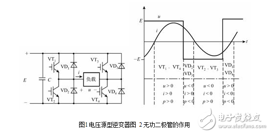
The voltage source inverter uses a capacitor as the energy storage component, and Figure 5-4 shows the schematic diagram of a single-phase bridge voltage source inverter. The voltage source inverter has the following characteristics:
(1) DC input side parallel large capacitor C is used as reactive power buffer link (filtering link), which constitutes the inverter's low impedance power supply internal resistance characteristic (voltage source characteristic), that is, the output voltage is determined, and its waveform is close to rectangular, current The waveform is load dependent and close to sinusoidal.
(2) Since the polarity of the DC side voltage is not allowed to change, the reactive current can only be changed from AC to DC feedback. For this reason, the freewheeling diode is connected in parallel with each power switching element to provide feedback energy for the inductive load current. Reactive path to DC. Figure 2 depicts the load voltage in a cycle? XML: NAMESPACE PREFIX = V /》 ![]() Load current
Load current ![]() Ideal waveform, press
Ideal waveform, press ![]() The flow of components and power in the polarity zone (P 0, power from DC to AC; P "0, from AC to DC", to illustrate the important role of VD for reactive power transfer.
The flow of components and power in the polarity zone (P 0, power from DC to AC; P "0, from AC to DC", to illustrate the important role of VD for reactive power transfer.
2. Current source inverter
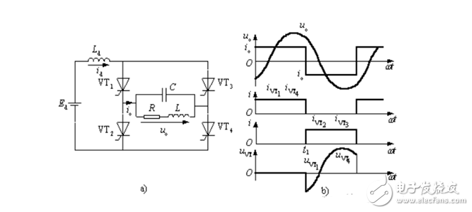
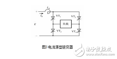
The current source inverter uses an inductor as the energy storage component. Figure 3 is a schematic diagram of a single-phase bridge current source inverter. The thyristor converter circuit is not shown. Current source inverters have the following features:
(1) The DC loop string uses the large inductance Ld as the reactive component (filter component) to store the reactive power, which constitutes the high-impedance power supply internal resistance characteristic (current source characteristic) of the inverter, that is, the output current is determined, and the waveform is close. Rectangular; the voltage waveform is related to the load, and the commutation voltage spike is superimposed on the sine wave.
(2) Since the DC link current Id cannot be reversed, only the polarity of the DC voltage across the inverter is changed to change the energy flow direction and feedback reactive power, and there is no need to set a feedback diode.
3. Comparison of two types of inverters
(1) The voltage source inverter uses a large capacitor as the energy storage (filtering) component, and the inverter exhibits a low internal resistance characteristic. The magnitude and polarity of the DC voltage cannot be changed, and the load voltage can be clamped to the power supply voltage level. Low surge voltage, suitable for stable frequency regulated power supply, irreversible electric drive system, multi-motor coordinated speed regulation and fast requirements.
The current direction of the current source inverter is constant, and the energy flow direction can be changed through the change of the working state of the inverter and the rectifier, and the electric and braking operation of the electric drive system can be realized, so it can be applied to frequent acceleration, deceleration, and positive , reversed single-machine drag system.
(2) The current source type inverter uses large inductance energy storage (filtering), and the main circuit has strong resistance to current surge, which can effectively suppress sudden change of current and delay the rising rate of fault current, and overcurrent protection is easy. The output voltage of the voltage source inverter is stable. Once the short-circuit current rises extremely fast, it is difficult to obtain the time required for protection processing, and overcurrent protection is difficult.
(3) The current source type inverter using the thyristor element relies on the resonance of the capacitor and the load inductor to realize the commutation, and the load constitutes a part of the commutation loop, and cannot be operated without being connected to the load system.
(4) The voltage source inverter must be equipped with a feedback (reactive) diode to provide an inductive reactive current path to the load. The main circuit structure is more complicated than the current source inverter. The reactive power of the current source inverter is stored by the filter inductor, which does not require diode freewheeling, and the main circuit has a simple structure.
Portable energy storage power Stastion
SHENZHEN CHONDEKUAI TECHNOLOGY CO.LTD , https://www.szsiheyi.com