Kaiyu brand intelligent switching power supply (also known as universal power module). It can be used for maintenance replacement of 14-inch--34-inch color TV, VCD, DvD and satellite receiver switching power supply. The original machine only needs to retain the rectification filter, spike absorbing circuit and secondary rectification part circuit. Significantly improve work efficiency during home repairs.
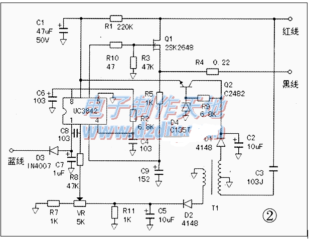
In order to understand the working principle of the power module. The author disassembles the module and draws out its schematic diagram. It can be seen from the schematic diagram that the module is similar to the switching power supply in the color display, that is, the typical uc3842+ FET scheme is used, the difference is that the blue is not connected. In the case of the line, the error samples are taken from the primary. uC3842 is a PwM switching power supply integrated controller with excellent performance, wide application and simple structure. Since it has only one output, it is mainly used for switching power supply at one end.
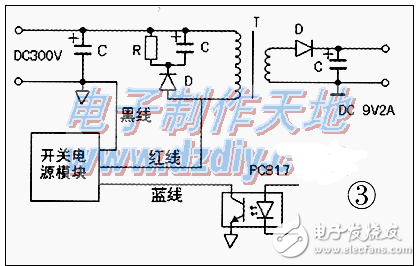
Debugging method: Connect the module to the circuit as shown in Figure 3, that is, the red wire is connected to the c-pole position of the original switch tube, the black wire is grounded, and the blue wire is connected to the photocouple 4 pin for standby of the remote control (if the original machine is step-down standby, Then you need to string in 5kΩ ~ 10kΩ adjustable resistor). Disconnect all the loads in the original circuit and connect the 60w--100w bulb to the output as a dummy load. Check the power supply after the error, and monitor the output voltage with a multimeter to debug the trimming resistor on the module. Make the output voltage match the original machine, and the other groups of voltages will automatically adapt.
1. When there is a malfunction, check the 300V filter and the transformer is normal, and the load is short circuited. Whether the circuit related to remote shutdown is normal.
2. If overheating, interference or even howling, improve the absorption circuit of the original machine, R is about 39Ω/3W, C is 470pF~1000PF.
3. When a few switching transformers do not match the module, the main winding of the original transformer can be doubled. Try not to remove the core to avoid damage.
4. Blue line and precision voltage regulation function. Connecting it to the optocoupler will make the working voltage more stable. If the requirements are not met, check whether the original voltage regulator circuit is normal.
We are the dial thermometer manufacture and supplier in China, we have dial thermometer, Bimetal Thermometer, Digital Thermometer, solar thermometer, the measuring rang from -40℃ to 600℃, the diameter of thermometer from 30mm to 250mm, it use to heating technology, industrial and process industrial, etc. The material are SS304, SS316. Our bimetal is import from Japan. It`s more accurate and stable. The stem can be customize.
Dial Thermometer,Industrial Bimetal Thermometer,Digital Thermometer, solar thermometer
Changshu Herun Import & Export Co.,Ltd , https://www.herunchina.com