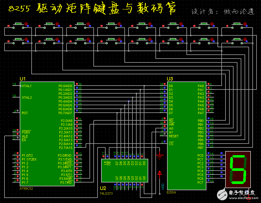
Assembly programming: matrix keyboard control digital switch display 0~F.
The following is a circuit diagram. 16 keys are required to display 0~F.
Seeing such a circuit and program can not help but think of a novice microcontroller scenario.
More than ten years ago, it was a Beihang book and it was such a program.
Later I read a few more books. There are also similar programs inside.
In fact, this program is very indiscriminate.
It put the line number, very clear. Also deliberately made into several branches.
When you change a line, the line number is stored in 00H, 08H, 10H, 18H.
The idea is also stupid. In fact, as long as you add 8, you can write a loop program.
There are lots of things that should be simplified in the program.
This procedural study really wastes me a lot of time.
According to the circuit and program in the title, the procedure for rewriting is as follows.
;
ORG 0000H
SJMP START
ORG 0030H
;--------------------------------------
DUMA:
DB 3FH, 06H, 5BH, 4FH, 66H, 6DH, 7DH, 07H // Co-inset segment code
DB 7FH, 6FH, 77H, 7CH, 39H, 5EH, 79H, 71H
;--------------------------------------
START:
MOV DPTR, #7F03H //8255 initialization
MOV A, #90H
MOVX @DPTR, A
MOV A, #16
;--------------------------------------
KEY1:
ACALL KS1 / / judge whether the key is pressed, return PA port state stored in A
JZ KEY1 // Return without
ACALL DELAY / / call delay subroutine
ACALL KS1 / / again to determine whether the key is pressed
JZ KEY1 // Return without
;
MOV R2, #0FEH // Initial column scan word
MOV R3, #8 //Check 8 times
MOV R4, #0 // Initial key number
LK4:
MOV DPTR, #7F01H //Point to PB port
MOV A, R2
MOVX @DPTR, A
MOV DPTR, #7F00H //Point to the PA port
MOVX A, @DPTR
JNB ACC.0, LK3
INC R4
JNB ACC.1, LK3
INC R4
MOV A, R2
RL A //If there is no, move left one column scan word and continue to judge the next column
MOV R2, A
DJNZ R3, LK4
LK3:
ACALL KS1
JNZ LK3 //Judge whether the pressed key has popped up.
;
MOV A, R4 //Key number in A
MOV DPTR, #0030H //point to the first part of the segment table
MOVC A, @A + DPTR //The key number turns into the corresponding segment code
MOV DPTR, #7F02H //Point to PC port
MOVX @DPTR, A //Digital Tube Display
;
SJMP KEY1
;--------------------------------------
KS1:
MOV DPTR, #7F01H //Point to PB port
MOV A, #0
MOVX @DPTR, A
MOV DPTR, #7F00H //Point to the PA port
MOVX A, @DPTR
CPL A
ANL A, #03H
RET //Return PA port data stored in A, If there is a key press, then A is not equal to zero
;--------------------------------------
DELAY: // delay subroutine, about 10ms
MOV R7, #20
D1: DJNZ R6, $
DJNZ R7, D1
RET
END
;======================================
The simulation screenshot of this program can be seen in the previous illustration.
The circuit in the title uses only one digital tube. There is still a gap between this and practical occasions.
If you use a dynamic display method to drive multiple digits, then the matrix keyboard's size can be expanded.
However, the procedure given here is not to increase a lot. Just adding three or five lines will suffice.
24W Interchangeable Power Adapter
24W Interchangeable Power Adapter,24V1A Interchangeable Power Adapter,Detachable Plug 12V2A Power Adapter,U L Cul Vi Switching Dc Adaptor
Guangdong Mingxin Power Technologies Co.,Ltd. , https://www.mxpowersupply.com