The early digital FM processing chip TEA5767 was developed by Philips and is widely used, but the chip requires an external audio amplifier circuit to drive the headphones. In view of this, domestic RADICO Microelectronics independently developed an FM stereo digital chip RDA5807P with high receiving sensitivity, which has excellent performances such as automatic search, subwoofer, mute, hibernation, and direct drive headphones. This article describes the design and production of a radio with remote control using the RDA5807P chip.
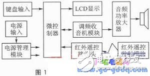
1 radio overall designThe overall design block diagram of the radio is shown in Figure 1. The radio uses a single 3.7 V lithium battery with a capacity of 1500 mAh as the power source. It can be charged repeatedly by the mobile phone charger during the service life. It is very convenient to use. Using low-power AVR microcontroller ATmega8L as the microcontroller, it is responsible for processing and coordinating the work of each module circuit. ATmega8L's working voltage is 2.7~5.5 V, and there are 512 bytes of EEPROM on the chip. It can be used without special external EEPROM chip. The channel and volume information of the receiving station before the power failure is saved, and the original information can be restored after the power is turned on again. The FM radio module is composed of a domestic chip RDA5807P plus a small number of peripheral components. The microcontroller writes/reads the internal registers of the chip through the I2C bus interface. Automatic search, manual channel selection, volume adjustment, and mute operation can be performed through the keyboard or infrared remote control transmitter. The LCD is used to display information such as the frequency and volume level of the currently listening station. The audio power amplifier amplifies the audio signal currently listening to the radio and drives the speaker to make a sound.
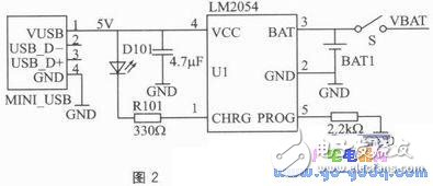
2.1 Power Management Module Circuit Design
The power management module circuit is shown in Figure 2. The LM2054 is a single-cell lithium battery constant current, constant voltage linear charging chip with a maximum charging current of 800 mA. It requires only a small external component and presets a 4.2 V charging voltage with an accuracy of ±1%. When charging, if the voltage of the lithium battery is lower than 4.2V, the charging indicator D101 is on, and the indicator D101 is off after the charging reaches the preset value of 4.2V.
2.2 Microcontroller and keyboard, display, infrared remote control receiving circuit design
Microcontroller and keyboard, display, infrared remote control receiving circuit shown in Figure 3.
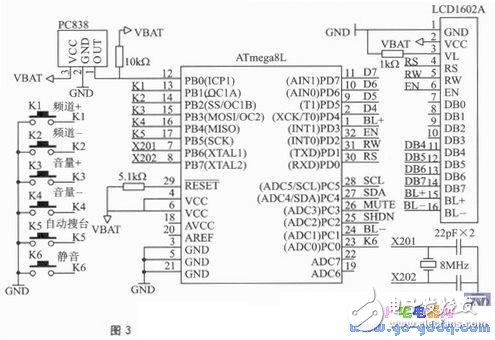
The keyboards K1 to K6 are used for frequency selection, volume adjustment, and the like. The infrared remote control receiving head is connected to the PB0 of the ATmega8L of the single chip microcomputer, and is decoded by the input capture function of the single chip microcomputer. In order to reduce the liquid crystal display LCD1602A occupying too many I/O ports of the MCU, the data interface only uses the upper 4 bits. When writing the command or data, it writes twice, first writes the upper 4 bits, then writes the lower 4 bits. In order to reduce the power consumption of the LCD, the backlight of the LCD is controlled by the PD3 and PC1 of the single chip microcomputer. When the user sets the station to be listened to, the LCD backlight automatically goes out after 5 s.
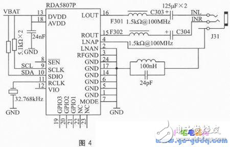
2.3 FM radio module circuit design
The FM radio module circuit is shown in Figure 4. RDA5807P is a domestic FM stereo radio receiver chip, with few external components and basically no need to calibrate, can receive European, American and Japanese FM bands through program settings. The MCU writes the address, command and data required to access the RDA5807P chip to the internal register through the I2C bus SCL and SDA. It can also read the data in the internal register of the chip through the bus to obtain the data and volume value of the receiving channel. Display usage. The output of RDA5807P can directly drive 32 Ω headphones to make sounds after suppressing high frequency interference by magnetic beads F301, F302 and capacitors C30 3 and C304. It can also be connected to the lower level audio amplifier to amplify and push the speaker to make sound.
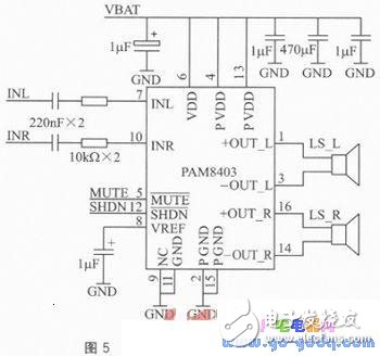
2.4 audio power amplifier circuit design
The audio power amplifier circuit is shown in Figure 5. The PAM8403 is a Class D audio power amplifier chip with low harmonic distortion, low noise crosstalk, and direct drive horn. The audio amplifier made with it has a simple circuit and reliable operation. It can output 3 W of power at 5 V supply and 4 Ω load. With an efficiency of over 90%, it is ideal for battery-powered portable electronics. In the circuit
The pin can be controlled by the microcontroller to output a low level to mute and turn off the amplifier system.
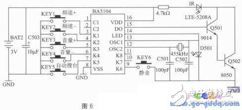
2.5 Infrared transmitting module circuit design
The infrared remote transmitter circuit is shown in Figure 6. BA5104 is an infrared remote control coding chip with pull-up resistor inside. When there is no key press, there is no current flowing in the circuit. The oscillation circuit can't
Vibration, no remote control code signal output. When a key is pressed, the circuit generates an 455 kHz oscillating signal, which is divided by 12 by the BA5104 internal circuit to obtain a carrier signal of 38 kHz. At this time, the coding information of the button and the state information of the C1 and C2 pins encode and modulate the 38 kHz carrier, and the 15-pin serial output is amplified by the Darlington drive circuit composed of the transistors Q501 and Q502, and the external transmission tube is The space is transmitted, while the 14-pin output is high, and the emission status indicator D501 is lit.
D-sub Connector Contacts
A D-sub connector is a form of connector commonly found in electronic and computer systems. It consists of a D shaped metal band and two or more parallel rows of either pin contacts (male) or socket contacts (female). D-sub connector contacts can vary in size, material, current rating, length and resistance.
The most common type of connector is the crimp contact. These are assembled by inserting a stripped wire end into the cavity at the rear of the contact. The cavity is then crushed using a crimp tool, gripping the contact to the wire.
What are D-sub connector contacts used for?
The D-sub connector contacts carry the signal from the source to the destination across the D–sub connection.
Types of D-sub connector contacts
Most D-sub connectors are supplied with contacts ready in place. Contacts can be replaced if damaged or if the application of the D-sub connector is to be changed from the original design specification.
High-current, high-voltage, or co-axial inserts require larger contacts. The material of the D-sub connector contact can be changed if the robustness or quality of the connection needs to be improved.
D-SUB coaxial contact,D-Sub Connectors Contacts,D-Sub Plug Connectors Contact,D-Sub Receptacle Connectors Contact
ShenZhen Antenk Electronics Co,Ltd , https://www.antenkconn.com