Application of ADN8831 in temperature control of optical devices
Most devices in optical communication systems such as TOF, arrayed waveguide grating (AWG), erbium-doped fiber amplifier (EDFA), and lasers are very sensitive to temperature. Good temperature stability can not only bring stable output of optical parameters of each device, but also improve the performance and reliability of the entire communication system. Although the change of temperature brings adverse factors to our design, at the same time, the temperature characteristics of the device can also be used in the design process. Therefore, temperature control is an important task in the design of optical systems. This paper introduces the application of ADN8831 in TOF and TDC temperature control in terms of temperature stability and temperature effectiveness. The results show that its control accuracy meets the requirements for temperature control in the design process of optical devices.
1. Principle of temperature control
1.1 Thermoelectric cooler
Thermoelectric Cooler (TEC) utilizes the solid thermoelectric effect. Compared with other refrigeration technologies, TEC has the following advantages: simple structure, small size, fast startup, flexible control, reversible operation, etc. Therefore, TEC has been fully applied in the system design of optical device temperature control, especially in the device Its advantages are more obvious when the operating temperature range is wider.
Thermoelectric cooler is made up of a series of P-type N-type semiconductor pairs connected in series. Due to the Peltier effect, when a direct current is passed through the closed loop formed by the pair, the nodes at both ends will be respectively Endothermic and exothermic phenomena occur. As shown in Figure 1, the thermal effects of each galvanic couple are independent of each other, so they are parallel in the direction of heat, so that the heat transfer efficiency of TEC has been greatly improved. The TEC has two end faces. When voltage is applied across the TEC, current flows through the TEC in a certain direction. At this time, one end (hot end) of the TEC is heated and the other end (cold end) is cooled. When reversed, the direction of TEC heat transfer will change, the original hot end becomes the cold end, and the cold end becomes the hot end. Usually, the target object that needs to be controlled in temperature is placed on the cold end of the TEC, and the heat sink is placed on the hot end of the TEC. The direction of the current passing through the TEC is changed to heat or cool the target object. The greater the current through the TEC, the more heat transfer between the two ends of the TEC. When the current reaches a certain value, the heat released by the cold end is equal to the heat absorbed by the hot end, at this time the temperature of the cold end stops changing and the temperature of the target object reaches stability.
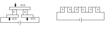
Figure 1, TEC structure diagram
1.2 Principle of temperature control
The TEC controller uses ADI's temperature control chip ADN8831. The entire process of TEC control is shown in Figure 2.
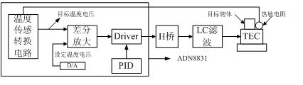
Figure 2. Block diagram of TEC control
The first part is temperature sensing. Its function is to feedback the temperature of the target object. In order to improve the accuracy and stability of the temperature, the thermistor should be as close as possible to the target object. The system uses a thermistor with a negative temperature coefficient, and the resistance becomes smaller as the temperature increases. The temperature-voltage conversion circuit, as shown in Figure 3, the target temperature induced is proportional to the output voltage.
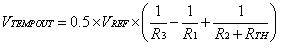 (1)
(1)
Define the lower temperature limit Tlow when Vtempout = 0V, the middle value TMID when Vtempout = VREF / 2, and the upper limit THIGH when Vtempout = VREF, so that you can set the temperature control range by changing the values ​​of R1, R2, R3.
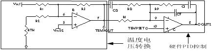
Figure 3, temperature and voltage conversion telephone and hardware PID control circuit
The second part is differential amplification. That is, the voltage corresponding to the target temperature is compared with the voltage at the set temperature point and then proportionally amplified.
The third part is the compensation network. The compensation network uses hardware PID (proportional-integral-derivative) control, which is composed of operational amplifier, resistor and capacitor. Its advantage is high reliability. The role of proportional adjustment is to reflect the deviation of the system in proportion. Once the system has a deviation, the proportional adjustment immediately takes effect to reduce the system deviation. A large proportional effect can speed up the system adjustment, but an excessively large proportional coefficient will lead to system instability. The function of integral adjustment is to make the system eliminate the steady-state error and improve the accuracy of the system, but at the same time it will also cause the system to respond slowly. The role of differential regulation is to reflect the rate of change of the deviation signal of the system, and can predict the trend of the deviation signal, so it can produce a leading control effect and change the dynamic performance of the system. In the actual adjustment process, attention should be paid to the problems of compromise overshoot and fast response. When the overshoot is serious, the proportional coefficient, integral time, and derivative time should be appropriately reduced. When the response speed is slow, the adjustment method is opposite to the above.
ADN8831 works as an H-bridge driver in linear and switching modes. Although the efficiency in linear mode is very low but the volume of peripheral devices is reduced, the switching mode is just the opposite, so this design achieves a complementary effect.
The fifth part is the H-bridge drive circuit composed of four power MOSFETs. The H-bridge is composed of two P-type and N-type power MOSFET pairs and TEC, respectively. Four MOSFETs form the four vertical legs of H, and TEC forms the horizontal bar of H. TEC is equivalent to a resistor with a small resistance, as shown in Figure 4. When ADN8831 drives Q1 and Q3 to turn on, the current flows through the TEC in the direction. The cold end of the TEC becomes the hot end to release heat to heat the target object. When Q2 and Q4 are turned on, the current flows through the TEC in the direction. The target object is cooled. Turn off the switching signals of two MOSFETs on any diagonal to make the current flow through the TEC in a single direction. At this time, ADN8831 can control the heating source except the TEC, such as heating sheet and high-power resistor.
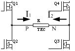
Figure 4, H-bridge structure controlled by TEC
The sixth part is the LC filter circuit. In order to improve the stability of the TEC temperature, the ripple current flowing through the TEC should be as small as possible. An LC filter circuit must be added after the H-bridge to filter out the PWM switching frequency to stabilize the TEC voltage. Although the high switching frequency reduces the volume of inductance and capacitance, but the same
Time will also bring the influence of EMI, so these factors should be considered in the system design.
2. Application of ADN8831
MEMS (Micro-Electro-Mechanical System) based FP (Fabry-Perot) cavity tunable optical filter (TOF), because the supporting material constituting the length of the cavity has a certain coefficient of thermal expansion, so when the ambient temperature changes, the cavity length It will change with the change of temperature, so that the center wavelength of TOF will drift, which will eventually affect the locking of the signal wave. In addition, by using the influence of temperature on the center wavelength, the starting wavelength can be shifted to the wavelength range required by the system by controlling the operating temperature of the TOF, thus overcoming the difficulty of controlling the starting wavelength in the process through temperature control.
The multi-wavelength tunable dispersion compensator (TDC) based on the GT (Gires-Tournois) etalon uses the GT etalon to make the optical path difference transmitted by different spectral components in the optical signal different, producing a periodic dispersion compensation effect. The factors that affect the optical path difference include the refractive index, cavity length, and angle of incidence of the etalon resonator. When the temperature of the GT cavity is changed, changes in the refractive index and cavity length will cause the optical path difference to change, causing the dispersion curve to shift. Thereby adjusting the dispersion. At this time, using the temperature characteristics of the material, as long as the temperature control accuracy is high and the response time is fast, a dynamically compensated TDC can be designed.
3. Experimental results and analysis
3.1 TOF stability and wavelength control experiment
Adjust the parameters of ADN8831 and set the controllable temperature range. Calculate the values ​​of R1, R2 and R3 by formula (1) when the set temperature is controlled at 50 ℃ -95 ℃. When the temperature is stable, the temperature voltage of the target object and the set temperature voltage are equal, so the voltage value corresponding to each temperature point is calculated by formula (1), and then the working temperature of the TOF is set by the DAC.
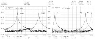
Due to the temperature sensitivity of the TOF chip, when the ambient temperature changes from -5 ° C to 65 ° C, the change of the center wavelength with temperature is shown in Figure 5-a. In the process, if there is no temperature control, the center wavelength will drift to 13nm towards the long wave . ADN8831 is used to control the TOF temperature at 92 ° C. Under the same ambient temperature change, the center wavelength drifts by only 0.5 nm, and the center wavelength stability is greatly improved. The control of temperature on the starting wavelength is shown in Figure 5-b. When the voltage is applied alone at normal temperature, the center wavelength can only reach 1557.94nm, so that it cannot meet the C-band signal filtering. The wavelength drifts towards the long wave. When the operating voltage is set to 65 ° C, the center wavelength drifts to 1563.32nm. Temperature control not only improves the stability of TOF but also improves the yield.
Wavelength (nm)
Figure 5-a Wavelength-temperature change Figure 5-b Temperature control of the starting wavelength
3.2 TDC dispersion compensation experiment
As a TEC controller, ADN8831 can also be used to control the heat source unidirectionally. The method is to remove a pair of MOSFETs on any diagonal of the bridge of Fig. 4H, thereby controlling the unidirectionality of the current to heat the target object.
Reducing the controllable temperature range can shorten the temperature stabilization time. Figure 6 illustrates the variation of the dispersion curve with temperature at different temperature points. When the temperature increases by 0.058 ° C, the dispersion curve drifts toward the long wave as a whole. For the ITU-T specific wavelength of 1550.52, the dispersion value is positive at 80.314 ° C. At this time, the operating temperature can be reduced to make the curve drift to the short wave, making the wavelength The dispersion value is negative, which in turn enables dynamic dispersion compensation.

Wavelength (nm)
Figure 6, dispersion curve at different temperature points
Conclusion
In order to improve the reliability of the system, stable temperature control is always a problem that must be solved in the design of optical devices. As a TEC controller, ADN8831's wide controllable temperature range and high control accuracy greatly improve the reliability of the device. At the same time, how to miniaturize the ADN8831 control circuit is a problem to be studied in the future.
Multifunctional Wood Grain Aroma Diffuser as below:
- Unique Modern Design. Appearance with wood grain finish, Wood Grain Diffuser can be a decorative piece for home rooms, office, hotel, yoga,etc.
- Bright And Dazzling LED Lights. Wood Grain Aroma Diffuser has 14 color changing night lights(bright and dim), you can cycle it through 14 colors or set it to one fixed color. The colorful light creat a romantic atmosphere.
- Whisper-quiet. Wood Grain Oil Diffuser is very quiet when working, it doesn't bother you working, learning and sleeping.
- Waterless Auto Shut-off. Wood Grain Essential Oil Diffuser will shutdown automatically when the water tank is short of water, no worry about safety.
- Timer Setting And Mist Control. 4 timer- 1H/ 3H/ 6H/ Continuous modes. Press the Mist button for 2 seconds, one beep for strong mist, two beep for weak mist.
- Aromatheray And Humidifier. Adding 3-5 drops of essential oil into the water, your room will fill with lovely fragrance and then you can enjoy aromatherapy. Diffuser can also be use as a humidifier without oils to add more moisture.
- Perfect Gifts. Aroma diffuser is the best choice as a gift, you can give it to your family, lovers and friends.
Wood Grain Diffuser
Wood Grain Diffuser,Wood Grain Oil Diffuser,Wood Grain Essential Oil Diffuser,Wood Grain Aroma Diffuser
Shenzhen Dituo Electronic Co.,Ltd. , https://www.sz-dituo.com