introduction
With the advancement and development of science and technology, the requirements for vehicle driving performance and safety and comfort have been greatly improved, resulting in a gradual increase in the number of electronic control units on the vehicle. However, the electronic control units on the vehicle (such as various switches, Devices, sensors, etc.) are still connected with traditional wiring harnesses, which makes the wiring harness in the vehicle too much and the wiring is complicated, which causes serious electromagnetic interference and reduces the reliability of the system. In high-end cars, electronic components and systems account for more than 20% of the price of the entire car, and there is an increasing trend. In this case, the electric control circuit in the car will be more complicated. How to network the devices in the car and reduce the number of wiring harnesses has become a key research direction for improving the system in the car.
In vehicle networking and communication systems, local network methods are becoming more and more abundant. Among them, network technologies such as CAN, Profibus, LON, ASI, EIB and eBus have developed quite maturely, and standardization of various network technologies has also been introduced. And, these mature network technologies have completed integration work. The CAN bus shows strong advantages in automotive applications in terms of stability, immediacy, and cost performance. As a LAN technology in distributed control, it has strong competitiveness. At present, many cars use the CAN bus to link the entire car control system for unified management, realize data sharing and coordinate with each other, make the wiring harness in the car convenient and reliable, improve the overall safety and cost performance of the car, and enhance its own competition force.
The prerequisite for the realization of networked control of vehicle systems is the intelligent design of network contacts, including the intelligentization of sensors, controllers and actuators. In this paper, the electronic control throttle is used as the research object, and the CAN bus intelligent contacts of the foot pedal position sensor, throttle position sensor and throttle position control actuator are designed. Based on this, a CAN bus control network is formed to complete the control Accurate control of valve position.
1 Vehicle CAN bus and distributed control system structure
Control area network (controller area network, CAN) is an industrial field bus, which is a communication protocol developed by the German Bosch company in the early 1980s as a solution to the data exchange between many control and test instruments in modern cars. In November 1993, ISO officially promulgated the international standard for high-speed communication CAN (ISO 11898). The collection of field data in the CAN bus system is done by sensors. At present, there are not many types of sensors with a CAN bus interface, and the price is relatively expensive.
There are a large number of sensors, electronic control units, actuators, etc. in the vehicle control system. Generally, multiple controllers share the same sensor information, and the real-time and fast requirements are high. How to connect them to form a distributed control network system It is an important development direction of modern control systems. Field bus control system (field control system, FCS) is one of the typical realization of control network structure. CAN belongs to the field bus category. It is a multi-master serial bus that effectively supports distributed control or real-time control. It is interconnected by field devices with its short message frames and excellent CSMA / BA bit-by-bit arbitration protocol. Favored.
The vehicle distributed control network system based on CAN bus is shown in Figure 1. It uses a field bus distributed system (FDCS) structure, which is composed of sensors, actuators, intelligent nodes of the controller and CAN field control network. Multiple intelligent nodes independently complete data collection, system setting, operation control, etc. Through the CAN field bus, various intelligent nodes exchange various data and management control information. 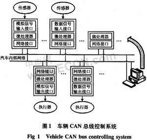
2 Principle and structure of wire-controlled electronic throttle system
The electronic throttle control technology first appeared in the early 1980s and was initially used only in high-end cars. With the increasing development of electronic technology, the increasingly prominent energy problems and environmental problems and the improvement of automotive performance requirements, electronic throttles have become the most important control devices on fully electronically controlled engines, and have begun to be widely used in various vehicles. The advantage is that the throttle can be quickly and accurately controlled at the optimal opening according to the driver's wishes, emissions, fuel consumption and safety requirements, and various control functions can be set to improve driving safety and comfort. At present, there are companies such as BMW, BOSCH, Toyota, etc. who are studying this technology, and manufacturers such as BMW, GM, Toyota, AUDI, etc. have been successfully applied to some of their models.
As shown in FIG. 2, the system is composed of an accelerator pedal position sensor and an electronic throttle body. The throttle body includes an actuator, a throttle valve, and a throttle position sensor. They are packaged as one. The actuator consists of a DC motor and related transmission components. The accelerator pedal is a high-precision linear potentiometer. As the sensor device for the throttle opening desired by the driver, its output is an analog voltage signal proportional to the stroke of the foot pedal; the throttle body consists of two parts: forward and reverse. The position sensor is used as the feedback signal of the throttle opening in the control. It obtains the corresponding voltage feedback value at the current opening through a pair of high-precision potentiometers inside the throttle body. The feedback value changes linearly with the throttle opening angle.

3 Intelligent sensor CAN bus interface design
The design of the smart sensor contacts is based on Microchip's PIC16F877A microcontroller and independent CAN bus controller MCP2510 and CAN transceiver PCA82C250.
PIC16F877A adopts high-performance 8 of RISC instruction system as a microprocessor, Harvard bus structure, low power consumption and high speed. Internally integrated ADC, serial peripheral interface (SPI) and Flash program memory, with multiple functions such as PWM output. PIC16F877A can realize seamless connection with CAN controller MCP2510 through SPI interface.
The hardware schematic diagram of CAN intelligent sensor node based on PIC16F877A is shown in Figure 3.
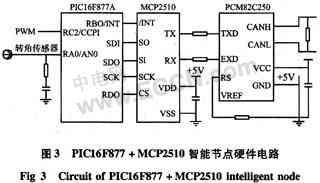
The communication module of the intelligent sensor CAN node is composed of an independent CAN controller MCP2510 and a CAN transceiver PCA82C250. MCP2510 can complete all functions of the physical layer and data link layer of the CAN bus, supports high-speed SPI interface (the highest data transmission rate can reach 5MB / s), and supports CAN2.0A / CAN2.0B protocol. The CAN transceiver PCA82C250 is the interface between the CAN controller and the physical bus. It provides differential transmission capability to the physical bus and differential reception capability to the CAN controller. At the same time, it can increase the communication distance and improve the embedded CAN intelligent node. Anti-interference ability.
PIC16F877A is connected to CAN controller MCP2510 through SPI, its serial data input (SDI) pin is connected to SO pin of MCP2510, its serial data output (SDO) pin is connected to SI pin of MCP2510, and its serial clock (SCK) pin Connect with the SCK pin of MCP2510. The reset signal and chip select signal of MCP2510 are provided by the single chip microcomputer.
The SPI interface works in active mode by setting the SPI interface status register and control register of the PIC16F877A. The timing when PIC16F877A communicates with MCP2510 is very important. When sending data, send the write command first, then send the register address, and finally send the data. When the MCP2510 receives the data from the bus, it will generate an interrupt. The MCU responds to the interrupt. When reading the data, it sends the read command first, and then sends the register address. The data is automatically written into the buffer of the MCU SPI interface.
Because the MCU itself has a 10-bit A / D converter, the analog signals output by the foot pedal position sensor and the throttle position sensor are directly connected to the MCU for digital-to-analog conversion, without adding a new A / D conversion device. In Figure 3, the sensor is input via RA0 / AN0. In order to filter out high-frequency noise, an RC filter circuit is connected to the analog-to-digital input port. At the same time, in the control of the DC motor of the electronic throttle device actuator, the PIC16F877A has a PWM port, which can drive the DC motor by connecting the drive circuit. The driver of this device uses L298.
The complete set of CAN bus control network is composed of foot pedal intelligent position sensor node, throttle body position sensor and actuator node and controller node. Among them, foot pedal intelligent position sensor node, throttle body position sensor and actuator node are composed of single chip The CAN bus mechanism is completed. Its main function is to transmit the pedal position and feedback signal to the controller, and the throttle position signal. At the same time, it receives the drive command signal from the controller to the actuator. The controller uses a microcomputer to implement CAN bus communication and the corresponding control algorithm through Advantech's PCL-841 card to complete the control of the wire-controlled electronic throttle.
4 System control principles and experimental results
The system control flow is shown in Figure 4.
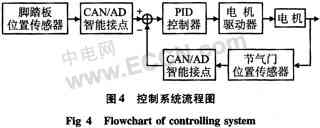
The control system is a closed-loop control process. The foot pedal position sensor is used as the input of the system. After A / D conversion, it is sent to the controller through the CAN bus. Similarly, the throttle position sensor is used as a feedback signal. After A / D conversion, it is sent to the controller through the CAN bus. The two signals are compared in the controller, and the controller uses the corresponding control algorithm (such as PID) to make decisions. The result is sent by the CAN bus to the throttle body position sensor and the actuator node. The microprocessor of the node generates a corresponding PWM signal to drive the operation of the actuator via the drive device.
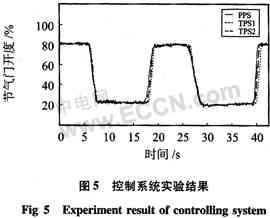
In order to verify the performance of the control system, an adaptive PID control algorithm was used to carry out the experimental platform and real vehicle experiment. The experimental results are shown in Figure 5. Among them, PPS represents the position of the foot pedal, TPS1 represents the experimental result of the throttle position under the experimental platform, and TPS2 represents the experimental result of the throttle position under the actual vehicle. From the control results, it can meet the real-time and precision requirements of electronic throttle control. At the same time, after the test of the actual vehicle environment, the system has a certain anti-noise ability.
5 Conclusion
As a reliable automotive computer network bus, the CAN bus has been applied in many advanced automobiles. The CAN bus is used in smart sensors so that the signals obtained by the sensors can be transmitted through the bus in real time, reliably, at high speed, and accurately. It enables each car computer control unit to share all information and resources through the CAN bus, to simplify wiring, reduce the number of sensors, avoid duplication of control functions, improve system reliability, reduce costs, and better match and coordinate each control system. At the same time, because the entire smart sensor network uses fully digital communication, the bus also has good anti-interference ability, which is the future development trend of smart sensors and smart control networks.
LED street lamp refers to the street lamp made with LED light source, which has the unique advantages of high efficiency, safety, energy saving, environmental protection, long life, fast response speed, high color rendering index, and is of great significance to urban lighting energy saving.
Led Road Light,Led Off Road Lights,Led Roadway Lighting,Cob Led Road Light
Yangzhou Heli Photoelectric Co., Ltd. , https://www.heli-eee.com