System introduction The electro-hydraulic power steering system (EHPS) is mainly composed of the following parts. They are power steering control unit (ECU), power steering sensor, gear pump with electric pump, oil storage tank, steering transmission device, CAN bus system. Our main work is to assist the research and development of the software and hardware of the steering control unit (ECU). The power steering control unit is mainly based on the signal from the power steering sensor, and the speed of the electric pump is controlled by considering the vehicle speed on the CAN bus, and then the pump oil amount of the gear pump is controlled to control the power steering transmission device. In this way, we can determine the amount of steering assistance we currently need based on the steering angle speed of the vehicle's steering wheel and the current driving speed of the vehicle.
1. ECU design summary
1.1 CPU selection of ECU The key to the design of the controller (ECU) is to select a single-chip microcomputer suitable for a specific control target. For the vehicle's electro-hydraulic power steering system, it requires the following characteristics of the single-chip microcomputer:
①Anti-environmental interference, meet the requirements of automotive chip temperature range, namely -40 ~ +125 ℃.
â‘¡ There are more I / O ports to realize multiple control functions; fast calculation speed to meet real-time control requirements.
â‘¢ Adopt a standard communication interface to facilitate the realization of diagnostic functions, and at the same time have the ability to communicate with other CPUs on the vehicle.
â‘£ It has a good performance-price ratio and is convenient for batch loading, making it a popular product.
Based on the above characteristics, the use of 16-bit single-chip microcomputer is a moderate choice for the electro-hydraulic power steering system. And most of the foreign electrohydraulic power steering system products currently use this grade of single chip microcomputer. Infineon XC164CM is this moderate product, it is a 16-bit microcontroller designed by Infineon for vehicle control system.
1.2 ECU module design 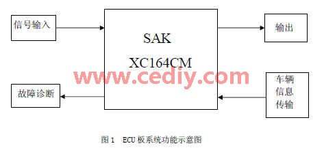
As shown in Figure 1, the design is based on the Infineon XC164CM microcontroller, which includes four modules: input, output, fault diagnosis, and vehicle information data transmission.
â‘ The input module input adopts XC164CM's input capture function CAPCOM unit, and each input channel corresponds to an independent CAPCOM channel. The CAPCOM channel can issue an interrupt after each event is received. It has a capture register CCx, which can hold 1 event. Because the interrupt address is independent, it is no longer necessary to identify which interrupt source enters the interrupt service program, which improves the efficiency of interrupt service processing. In this system, CC16 and CC17 are also used as the input signal catching channels for two Hall device pulses, and CC23 is used as the input signal catching channel for steering wheel angle pulses. Using the CAPCOM channel greatly improves the quality of the collected signal, the CPU takes less time, and the resolution of the CAPCOM capture event is 400 ns at a 20MHz main frequency.
â‘¡Output module
XC164CM has 47 I / O ports. In this system, P1 port is used as the control output port. Each I / O port uses an independent controller to control the input / output.
â‘¢Diagnostic module
EHPS is a system with high reliability requirements. It requires internal programs to monitor the system at any time. Once a failure occurs, it can be recorded in time and stored. This system uses the E2 PROM of the I2C bus as the fault code memory, and uses the synchronous serial function of the XC164CM to realize the communication between the I2C bus and the E2PROM, the XC164CM as the master, and the E2PROM as the slave. The external diagnosis communication is realized through the CAN1 port of XC164CM, and the communication with the PC is through a USB data acquisition card.
â‘£ The vehicle information data transmission single chip microcomputer XC164CM has two CAN bus controllers, CAN1 and CAN2. There is a 2K byte CAN register space to realize CAN communication. It has 32 information bodies, and each information body has 8 bytes of data that can be transmitted. The vehicle speed and engine speed required by the EHPS system are passed 2. ECU software design The program structure adopts the popular multi-module structure in C language. Compared with the previous single module structure, this structure has a clear program structure, which is convenient for program transplantation and program maintenance.
2.1 Main program of EHPS ECU
The EHPS main loop is a timed loop calling program. The program block diagram is shown in Figure 2. 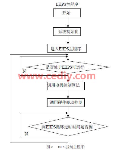
It mainly calls each subroutine. The timing time should be based on the complexity of the algorithm. When the algorithm is more complex and time-consuming, the cycle time can be defined longer. If the CPU function is strong, and the algorithm is relatively simple, you can use a relatively short cycle time. For example, 5ms or less. Some time-consuming programs, such as diagnostic programs, can be called outside the EHPS main loop. Every time the program starts to execute, it needs to call the initialization program, first initialize the hardware peripherals, such as serial port, timer, etc. These initializations are only defined once each time the power is turned on, and interrupts must be opened, and then software initialization must be performed to set the threshold for EHPS control. Some of these thresholds change during the control process, and some are constant constants. If it is a constant, it can be defined by the method of macro definition in C language. Calling the diagnostic program is a comprehensive diagnosis of the system. This procedure takes a long time, so it is only outside the EHPS main loop. The EHPS system enters the EHPS cycle after completing preparations. EHPS cycle can generally be defined as between 4 ~ 50ms. When calling various algorithms between this time, it is necessary to ensure that the total running time of each program is less than the EHPS cycle time, so as to ensure the rhythm of EHPS. If the program execution time is greater than the EHPS cycle time, the program will not work well, resulting in unstable system operation. The EHPS cycle time is adjustable, that is, it should be adjusted according to the execution time of the program.
2.2 Interruption procedure of EHPS ECU
The operation of the EHPS main loop is interrupted by the interrupt system from time to time. Once an interrupt occurs, the CPU should respond to the interrupt and exit the main loop. The service program of the interrupt system mainly deals with sudden and random events. If there is no interruption, it will occupy a lot of query time of the main program, so the interrupt system is actually a parallel multitasking program.
The following types of interrupts are mainly used in EHPS software:
1) Steering wheel angle interrupt: It uses input capture interrupt to record the steering wheel angle pulse signal to the register, which is used to calculate the target speed.
2) Motor speed acquisition interrupt: It uses input capture interrupt to record the input speed pulse signal to the register at any time.
3) Serial communication interruption: Serial communication is mainly used to diagnose the system, using the receiving interruption, after receiving the host computer signal, you can interrupt the main loop and enter the diagnostic program.
4) Timer interrupt: delay processing of the control system.
3. ECU hardware circuit system design The electronic control unit determines and controls the motor speed and drive current according to the steering speed and vehicle speed signals. So that it can get the most optimized steering assist torque at every speed. In order to protect the power drive circuit, the motor current needs to be sampled. In order to reduce the acquisition noise, a first-stage sample-and-hold circuit is used for the system current input. The differential input terminal passes through the sample-and-hold. sampling. The principle of the motor current differential amplifier circuit is shown in Figure 3. In order to improve the anti-interference ability of the system, a 5mV bias voltage is added to the input terminal. In order to control the current commutation time of the motor, two Hall speed sensors are used to accurately control the commutation of the motor. Hall speed sensor can adopt TLE4905. In order to control the speed of the motor, PWM chopping is used to control the motor voltage. The phase of the motor is controlled by P1L0 ~ P1L3 of P1 port of XC164CM, the voltage is chopped by CC24 and CC25 of P1 port, the waveform is superimposed by 74LS366 and then sent to the power MOSFET. 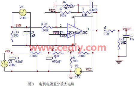
4. Comparison of test results
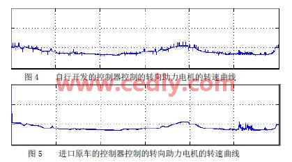
We used MATLAB / Simulink control development and test platform to simulate the test of our EHPS system. Figure 4 and Figure 5 are the comparison of the control effect of the self-developed ECU and the ECU on the imported original car. The control effects of the two controllers are consistent. At the same time, we conducted a driving experience by different drivers. Without telling which controller in advance, the driver can't tell whether it is the ECU on the original car or the ECU developed by itself.
Conclusion In the course of nearly two years of research, we mainly used online debugging of the control program on the real car, and compared it with similar products abroad. This ensures the feasibility of the product in real vehicles. According to the motor control curve of similar foreign products, our EHPS ECU has basically reached the level of similar foreign products in terms of performance. However, reliability must be further verified as the product continues to be loaded.
Make your business brand or logo stand out in ways common signage simply can`t match!
A great way to make your company name, logo or promotional message stand out, custom Neon Sign Logo is a specialty.
Neon Sign Logo
Neon Sign Logo,Custom Led Logo,Light Up Logo Signs,Led Logo
Shenzhen Oleda Technology Co.,Ltd , https://www.baiyangsign.com