This article refers to the address: http://
Cars are currently the main means of transportation for human beings and a symbol of modern civilization. The world's annual car sales have reached more than 60 million, and the number of cars has exceeded 500 million. The more cars that are stolen, the more cars are stolen. Therefore, car theft has become an important social issue. It has been listed as four major issues in the development of automotive technology along with safety, environmental protection and energy conservation.
Car anti-theft devices can be divided into three categories according to their structure and function: mechanical, network and electronic. The mechanical anti-theft principle is to lock a structure on the car with a mechanical lock, such as a transmission, a steering wheel, and the like. The anti-theft device is easy to install and cheap, but its volume is large, and the anti-theft device of this type only has no anti-theft alarm and cannot ensure theft prevention. Network-based anti-theft mainly relies on the public network of the society to monitor the driving of vehicles, such as GPS positioning system, GSM or GPRS. The anti-theft device is advanced in technology and powerful in function, but the price is high, the service fee is required, and the communication signal is easily interfered. To reduce the anti-theft performance. The electronic anti-theft device is the most popular anti-theft device in the automobile market. It can realize one-way or even two-way alarm by using the radio transmitting chip in the key to communicate with the ECU in the vehicle body. When the car is invaded by the outside world, the owner of the car can understand the condition of the car through the display on the key that is carried with him, but the disadvantage is that the false alarm rate is high.
This paper presents a two-way electronic car anti-theft system based on single-chip microcomputer, which consists of two parts: the main unit and the remote control. The remote control is carried by the owner of the vehicle, and the host is placed in the vehicle to detect the alarm signal source, and the wireless transceiver module is used for half-duplex communication between the two.
1 host hardware design
The host is placed in the car and consists of five modules: MCU, power supply, sensor input, high frequency module and alarm output. The system block diagram is shown in Figure 1. The main controller MCU adopts LPC930, which is used to detect the trigger of the sensor and generate an alarm signal; at the same time, the state of the remote controller is updated to realize the synchronous alarm. Since the sensor input module requires a DC voltage of 12 V and the LPC930 operates between 2.4 and 3.6 V, the SPX1117 regulator is used in the power module to generate a 3.3 V DC voltage. The sound alarm control circuit uses RT0100 circuit. RT0100 is a crystal circuit that can generate a single sound. It is manufactured by CMOS technology and has built-in RC oscillator circuit. The working voltage is 2~5 V and low quiescent current.
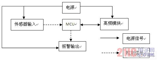
Figure 1 System block diagram of the host
1.1 Sensor module design
The sensor module includes a side gate detection circuit and a vibration detection circuit. When various alarms are triggered, the car horn alarms for 30 s, the direction light flashes, and the vehicle fails to start. After the alarm is completed, the anti-theft system automatically returns to the state before the alarm. If the same sensor is detected continuously in a short time, the anti-theft system will automatically stop the alarm after only 4 minutes of alarm. All detection points are re-detected until other sensors are triggered. At this time, the same sensor is detected to be triggered and alarmed again for 4 min.
1.1.1 Side Door Detection Circuit
When the host is in the armed state, the side door detection circuit is used to detect whether the side door is opened. If the side door is opened for no reason, the host enters an alarm state. The detection circuit is shown in Figure 2. In the figure, point A is connected to the side door, and point B is connected to the single chip microcomputer. When the side gate is closed, point B is charged to a high level because diode D2 is reversed. When the side door is opened, point A becomes low level, diode D2 is turned on, relay switch is grounded, RC circuit composed of C1 and R2 is rapidly discharged, point B is pulled low, and a low level signal is generated to the single chip microcomputer. The single chip microcomputer controls the alarm output circuit alarm.
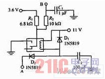
Figure 2 side door detection circuit diagram
C2 is used to filter low-level glitch pulses to avoid system malfunction. Diode D1 and the relay coil form a bleeder circuit. When the side gate is closed, the remaining charge is discharged through D1 due to the inductance of the relay coil.
1.1.2 Vibration detection circuit
When the host is in the alert state, the vibration detecting circuit is used to detect whether the external interference causes the body damage. If the body vibration caused by the external interference exceeds the limit that the vehicle body can withstand, the host enters an alarm state. The circuit diagram is shown in Figure 3. The point A is connected to the vibration detecting sensor, and the point B is connected to the single chip microcomputer. When vibration is detected, A goes low, D1 turns on, and the RC circuit composed of C1 and R2 is rapidly discharged through D1, causing point B to quickly go low. The voltage across C1 cannot be hopped, so this feature is used to filter the low-level glitch generated by the vibration to ensure accurate detection of the vibration hopping signal.
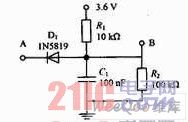
Figure 3 vibration detection circuit diagram
1.2 Alarm output module
In addition to simple sound and light alarms of the horn and the light, the alarm output module also uses a flameout output control circuit. When the host is in an alarm state, the vehicle is turned off and cannot be started. The circuit diagram is shown in Figure 4, where point A is connected to the flameout output controller, and point B is connected to the microcontroller. When the MCU outputs a high level, the transistor Q1 is turned on, and the A point becomes a high level, and a flameout output signal is generated, and the car cannot be started. Transistor Q2 acts as a shunt protection. When the emitter current of the transistor Q1 exceeds the upper limit, Q2 will be automatically turned on to prevent the Q1 from being damaged due to overcurrent. The varistor RU1 protects Q1 and Q2. When the collector voltage of Q1 does not exceed the upper limit, RU1 will not conduct. However, when Q1 is overvoltage, RU1 is automatically turned on to avoid damage of Q1 during overvoltage.
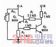
Figure 4 alarm output module
2 remote control hardware design
The remote control part is composed of an MCU, a wireless transceiver module, a power supply, a keyboard, and an alarm module. The LPC930 is used as a core device to control the operation of each module around it. The wireless transceiver module with TDA5255 as the core receives the data transmitted from the host and forwards it to the LPC930 for processing. The system block diagram of the remote control part is shown in Figure 5.
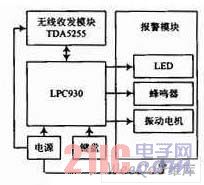
Figure 5 System block diagram of the remote control section
The wireless transceiver module consists of four parts: antenna, high frequency transmission, high frequency reception and TDA5255. The TDA5255 chip is a powerful low-power FSK/ASK single-chip transceiver chip manufactured by Infineon, Germany. It operates in the 433-435 MHz band and has FSK/ASK modulation and demodulation functions. High integration, complete VCO (voltage controlled oscillator) and PLL (phase locked loop) synthesizer, FSK modulator, RSSI limiter, FSK demodulator, data filter, data splitter, etc., reducing the periphery Circuit design. More importantly, the chip has a power-saving mode function, and the power-saving mode can be set in different ways to meet the low power consumption requirements of the remote controller. The system block diagram of the module is shown in Figure 6.
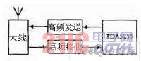
Figure 6 System block diagram of the module
3 system software design
3.1 Host Software Design
The software part of the main computer mainly includes wireless data transmission, data processing and backhaul, sensor detection, alarm output and backhaul. There are more than 20 kinds of status and functions to be processed, and real-time performance, and remote control There is good interactivity. The two variables STATUS and D-STATUS are used to store the state of the system and alarm respectively, and jump according to the state. The overall flow block diagram is shown in Figure 7.
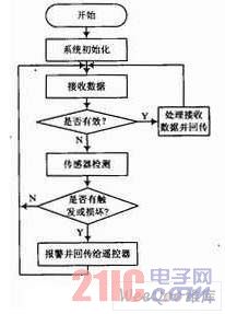
Figure 7 overall process block diagram
3.2 Remote control software design
The remote control software is designed with the button as the first response, and the data reception is the second response. In addition to the functions of data transmission, alarm, button defense, and release, music generation, low voltage detection, low power control, and signal are also required. Additional features such as intensity detection. The software design flow chart is shown in Figure 8.
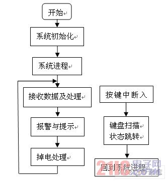
Figure 8 software design flow chart
4 Conclusion
The system adopts a single-chip microcomputer as the main control, and adopts a custom communication protocol to realize half-duplex communication between the host and the remote controller, thereby achieving the function of anti-theft alarm. The remote controller controls the state of the host, and can synchronize alarm with the host; the host can detect multiple trigger sources to realize the remote alarm of the host itself and the remote controller, and can complete the automatic locking of the door set by the remote controller, automatic alarm recovery, emergency alarm release, etc. Features. After testing, the system has the characteristics of strong real-time performance, high reliability and low power consumption.
This LCD Writing Board have no pen, no electricity, no dust, no ink just one press erasing.
This LCD Writing Pad Tablet subvert the writing revolution of paper and pen.
More than 100000 times writing life.
Conform to sustainable development mode One Electronic Drawing tablet can save 30 trees
This LCD Writing Tablet is the newest product, it is a mini writing board also it is a mobile phone shell(For Iphone size, this 4.7 inch shell suitables for Iphone 6/7/8 plus.


5.5 Inches LCD Writing Tablet,Writing Tablet,Boogie Board LCD,LCD Writing Tablets for Kids
Shenzhen New Wonderful Technology Co., Ltd. , http://www.sznewwonderful.com