The demand for lighting quality is now increasing. For office buildings, shopping mall lighting and outdoor floodlighting, there are two sources of light that deserve our attention. One is a high-intensity discharge lamp (HID), and the other is a high-power energy-saving lamp to be introduced in this article. The high-power energy-saving lamp can achieve a luminous efficiency of 80 lm/W, a color rendering index of more than 90, and a low-cost, long-life characteristic. For traditional energy-saving lamps, the power is generally below 35W, and the circuit that constitutes the ballast is relatively simple. It is usually realized by a self-excited circuit or a simple chip, and there is no power factor correction (PFC) function. But for high-power energy-saving lamps, such circuits are far from meeting their own requirements.
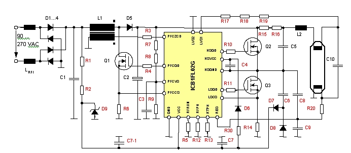
Figure 1: Circuit diagram of a 120W energy-saving lamp using ICB1FL02G.
Infineon Technologies' ICB1FL02G, a control chip for electronic ballasts for fluorescent lamps and high-power energy-saving lamps, contains unique control features and comprehensive protection functions to achieve single or multiple lamps with a minimum of external components. Tube operation. The chip integrates a PFC controller and a half-bridge control section and is optimized for the special requirements of the T5 lamp. The protection functions for the lamp are: programmable preheating to extend lamp life, end of life protection (EOL), capacitive mode protection, lamp rectification and DC status protection, lamp removal protection, and lighting voltage protection.
ICB1FL02G has two function modules. The first function module is the control of BOOST PFC circuit, and the second function module is the control of half bridge inverter circuit. In the PFC control circuit, the chip operates in a critical conduction mode and has a built-in digital PI filter. Compared to traditional control chips (such as the TDA4863), it reduces two pins. In the half-bridge inverter control circuit, the driver for driving the high-side floating MOSFET of the half-bridge is a patented technology that utilizes a chip-integrated hollow transformer, so that the high-low voltage isolation capability reaches 900V, meeting the needs of some special specifications. . The preheating frequency, warm-up time and lamp operating frequency of the ballast can only be set by external resistors. The high level of integration also makes it possible to compact in high power energy saving lamp applications.
120W energy saving lamp design
Next, take an OSW 120W energy-saving lamp as an example to elaborate on the design process. The circuit schematic is shown in Figure 1. The general parameters of the ballast are set as shown in Table 1:
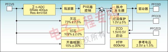
Figure 2: ICB1FL02 protection at the PFC pole.
When the main input signal is connected, current flows through R1 and R2 to charge capacitors C7 and C7-1. At this point, the current consumed by the chip is typically below 100μA until the supply voltage VCC reaches 10V. After this voltage is exceeded, a 20μA current is output at the RES terminal of the pin to detect the presence of the low-voltage side filament. As long as the voltage of the RES pin is lower than 1.6V, the filament is considered to be intact. At the same time, the high voltage side from the PFC output capacitor C2, there will be a current through the resistors R15 and R16 to the high side of the filament, and then this current flows into the LVS1 through the resistors R17, R18 and R19. When the current is greater than 15μA, the filament is considered intact. When the chip is used in a single-lamp energy-saving lamp, the unused LVS pin needs to be grounded to shield this detection function. If there is no abnormality in the detection, the chip enters the normal working state, and the half-bridge driving circuit starts to work.
PFC pole working principle and design
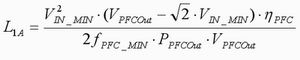
While the inverter bridge is running, Q1 in the PFC BOOST converter also starts to work. The working principle is not much different from the control chip in the traditional critical conduction mode, but after the load is reduced to a certain extent, it will eventually enter the discontinuous mode (DCM). When to enter the DCM depends on the output of the internal digital PI filter. The switch operates in a zero voltage turn-on mode and its operating frequency varies with the input voltage. The PFC inductance can be determined by the minimum of the following three equations.

Figure 3: Frequency and lamp voltage changes from start-up to steady-state operation.
At the lowest input voltage:
At the highest input voltage:

When loading lightly into DCM:
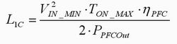
The PFC efficiency ηPFC is 0.95, and TON_MAX is fixed inside the IC, which is 23.5 μs. PFC has comprehensive protection functions covering PFC overvoltage, undervoltage, open loop and overcurrent protection. Its protection block diagram is shown in Figure 2. Therefore, when selecting the PFC pole voltage and current sampling resistor, pay attention to its corresponding protection threshold.
Half-bridge inverter circuit working principle
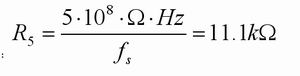
The typical working process of the ICB1FL02G inverter half-bridge circuit is shown in Figure 3. At first, the half-bridge inverter circuit operates at a fixed 125 kHz and is decremented by 16 steps to a preheating frequency determined by R12 within a fixed time of 10 ms. The warm-up time can be selected by adjusting the resistance of R13 between 0 and 2,000 ms. Then the operating frequency will continue to drop by 128 steps in 40ms, and finally run at the steady-state operating frequency determined by R5.
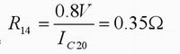
In the lighting state, because the resonant circuit has no load, the lamp will withstand high voltage, and a relatively large reactive current will flow in the resonant circuit. Resistor R14 detects this reactive current. When the voltage of the pin LSCS is detected above 0.8V, the operating frequency will stop falling, then rise for a while, then continue to fall until the 0.8V threshold is triggered again or the lamp is broken down. Through this test, if the lamp is not illuminated, the lighting state will increase from 40ms to 235ms, and the voltage on the lamp will maintain the set voltage. If the lamp has not broken down within 235ms after the end of warm-up, and the steady-state operating frequency cannot be reached, the IC will enter the fail-safe mode. It can be restarted by removing the lamp or restarting the input voltage.
C6, D7 and D8 at the output of the half-bridge form a charge pump that supplies power to the IC via C7. At the same time, C7 supplies power to the high-voltage side logic control supply capacitor C4 via R30 and D6. In addition, C6 can adjust the rate of change of voltage and can create conditions that produce zero voltage switching.
In the normal operation mode of the inverter bridge, if the operating frequency slightly deviates from the ZVS state and is close to the capacitive region of the resonant network, a spike current is generated when the switching transistor is turned on because of the switch-like charging of the charging pump capacitor C6. Such a situation is called Cap Mode 1. If this condition lasts for more than 500ms, the IC enters the failsafe mode. In the second case, the resonant network is completely in a capacitive state, and the MOS transistor has a large forward current flowing at the instant of turn-on. This condition is called Cap Mode 2 (Cap Mode 2). In this extremely high-loss operation, the IC will enter the fail-safe mode as long as it exceeds 610μs.
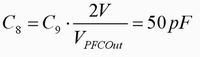
The detection of the capacitive mode is achieved by the partial pressure of the C8 and C9 capacitors. Each time the lower tube Q3 is turned on, if it is detected that the voltage of the RES pin exceeds the value of VREScap (typical value 0.24V) above VRESLLV, it enters the capacitive mode one. Each time the upper tube Q2 is turned on, if the voltage of the RES pin is detected to be lower than the VREScap value (0.24V) above VRESLLV, the capacitive mode 2 is entered. The protection point is shown in Figure 4.

Figure 4: Cap Mode 1 and Cap Mode 2 protection checkpoints.
Overcurrent detection of the inverter bridge is achieved by R14. In any case, when the voltage at the LSCS pin exceeds 1.6V and remains above 400ns, the chip enters fail-safe mode.
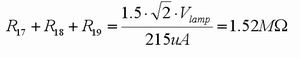
When the fluorescent lamp approaches the EOL state, the voltage of the lamp becomes asymmetrical or increases. The current flowing through the resistors R17, R18, and R19 is detected by the pin LVS, and the voltage on the lamp can be measured correspondingly. The current threshold for flowing into LVS through R17, R18, and R19 is ±215μA. When this current is exceeded, the lamp enters the end-of-life protection state after 610 μs. At the same time, if the lamp enters the half-breakdown state due to aging, the LVS pin will detect a DC current. If the DC current exceeds ±175μA, the chip will enter the end-of-life protection state after 610μs. In addition, when the LVS pin detects that the ratio of the secondary positive (negative) pole peak voltage to the next negative (positive) peak voltage exceeds 1.15 or lower than 0.85, the rectification effect state of the lamp voltage asymmetry is Will be detected. When this state exceeds 500ms, the IC will also enter the end-of-life protection mode. The LVS2 pin and the LVS1 pin are identical, and the unused LVS pin must be grounded under single lamp operating conditions.

Table 1: Ballast operating parameter settings.
Half-bridge inverter circuit design
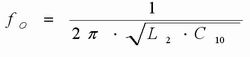
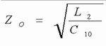
After understanding the working process and protection mode of ICB1FL02G, the parameters of the half-bridge inverter circuit can be designed. The first thing that needs to be determined is the parameters of the resonant networks L2 and C10.
Resonant network input voltage RMS:

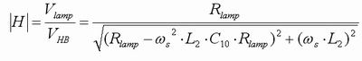
The steady-state operating resonant network gain must satisfy the following equation:

The filament current at steady state operation is IFila=0.44A, and then the preheating frequency fPH is calculated. Hypothesis
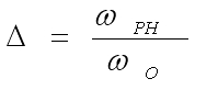
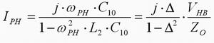
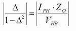
From the above formula, Δ can be obtained. It should be noted that the Δ value must be greater than 1, in order to achieve the ZVS operation of the half-bridge circuit during warm-up. Δ=1.46 is available. So preheating frequency

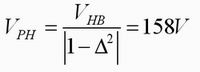
The lighting frequency can be obtained by:

Knowing the parameters fS, fPH, fIGN and TPH, the following parameters can be determined:
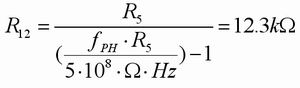
Set the steady state operating frequency:
Set the preheating frequency:
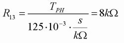
Set the warm-up time:
The peak current flowing through the resonant capacitor C10 when lighting is
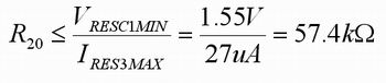
For current limiting resistors R15 and R16, this can be determined by the lowest input voltage and the highest LVS sink current. View the data sheet to see the highest LVS sink current ILVSSINKMAX = 26μA.
The low-end filament detecting resistor R20 of the lamp can be determined by the following formula
Summary of this article
This paper discusses the method of implementing high-power energy-saving lamp ballast with ICB1FL02G, introduces the working principle of ICB1FL02G, and designs the main parameters of the whole circuit based on OSRAM 120W high-power energy-saving lamp. The ballast implemented with this line has high power factor, programmable warm-up process, complete EOL protection, capacitive mode protection, and lamp removal protection. This method improves the service life and safety of the high-power energy-saving lamp, and achieves a good working state of the energy-saving lamp. In addition, the reduction of the peripheral circuit realizes the miniaturization and high reliability of the ballast.
1. Indoor LED Curtain Poster Display with price Advantage: We have the best competitive price in the market, we also have the same or even better quality.
2. Indoor LED Curtain Poster Display with quality advantage: From material to finished product, from design to production, we control all processes.
3. Indoor LED Curtain Poster Display service advantage: We also provide best service after sales and we prioritize every customer's needs.
4. We ensure that our LED Curtain Poster Display are CE certified, ROHS compliant, FCC identified.
5. Indoor LED Curtain Poster DisplayWith specially designed fast lock system, easy to install and dismantle.
6. The new structure design enablesIndoor LED Curtain Poster Display diversified installation to meet the hanging-up and stacking requirements.
7. Full Color Indoor LED Curtain Poster Display with High contrast rate up to 5000:1 by using black LED.
8. Indoor LED Curtain Poster Display with high refresh rate with NOVA control system, no scan line when photographed.
Indoor LED Curtain Light Box,LED Curtain Slim Light Box,LED Curtain Poster.
Shenzhen Macion Optoelectronics Technology Co.,Ltd. , https://www.macion-led.com