Design of plasma color TV based on Genesis gm5020 chip
Abstract: GM5020 is a highly integrated image processing chip produced by Genesis Canada for liquid crystal displays and other dot matrix displays. The characteristics, functions, and principles of the chip are introduced. And using gm5020 to design a plasma color TV, gives its hardware structure and software flow.
Plasma color electric energy is safe to avoid radiation, it is 100% green environmental protection TV. Because it is not affected by magnetic and magnetic fields, it has the advantages of slim body, light weight, large screen, bright colors, clear pictures, high brightness, low distortion, and space saving. Plasma color TV (PDP) realizes the three-in-one of TV, computer and telecommunication, which directly meets the requirements of broadband multimedia information network. PDP TV is one of the current directions of large-scale color TV. In the future digital era, it will gradually replace the huge box-shaped CPT display and become the dominant product in the future color TV market. Several of the world's largest PDP manufacturers have announced the launch of new PDP products, indicating that PDP has begun to leap onto the big stage of the display market. However, the high price of PDP severely restricts its popularity.
The flat panel display is designed with gm5020, which is simple, flexible and low cost. Most domestic and foreign LCD displays use this chip. We use gm5020 to design plasma color TV to reduce the cost of plasma color TV.
1. Features and functions of gm5020 gm5020 is a highly integrated image processing chip produced by Canadian genesis company for liquid crystal display (LCD) and other dot matrix displays. It has the following main features:
(1) Three ADC inputs (RGB), used as the input of computer graphics card;
(2) An 8-bit ITU-R BT656 video input signal (YUV) port;
(3) A digital video interactive interface (DVI), including high-bandwidth digital information encryption protection (HDCP);
(4) With image enlargement / reduction / freezing function;
(5) With on-screen display (OSD) control function;
(6) There is a single-chip computer with 8051 structure in the chip;
(7) With the function of frame rate conversion (FRC) control;
(8) The video working frequency is up to 160MHz;
(9) The highest resolution SXGA is 1280 × 1024;
(10) Provide an output interface that supports flat panel displays (LCD or PDP) and an output interface that supports CRT displays;
(11) Provide a 9-wire bidirectional data interface (GPIO) to connect with external MCU;
(12) A 2-wire I2C interface and a 6-wire I2C interface;
(13) It has the function of adjusting the chroma, contrast, brightness and saturation of RGB and YUV signals.
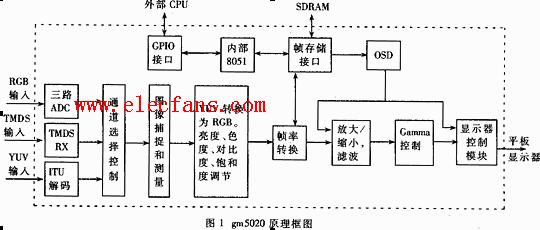
The power supply voltage of gm5020 is 3.3V, and it adopts 292pin and 27mm × 27mm PBGA package. The gm5020 functional block diagram is shown in Figure 1. Except for four external clocks, all clocks are generated by gm5020 through direct digital synchronization (DDS) to generate the required synchronization clock.
There are two reset methods for gm5020: hardware reset and software reset. Hardware reset refers to resetting the reset pin (T1) of gm5020 to low level for 1μs to reset gm5020. Software reset refers to resetting gm5020 by setting bit SOFTWARE_RESET = 0 in register HOST_CONTROL.
gm5020 can receive three input data modes: (1) 24bit RGB; (2) 8bit ITU-RBT656 (CCIR626 422); (3) Digital video interactive signal DVI.
The gm5020 can measure the line scan (HS) and field scan (VS) time parameters of the input video signal and is used to detect whether the input video signal has changed and determine the mode of the input video signal.
The gm5020 can adjust the background, brightness, chroma, contrast and saturation of the captured digital image data.
There are independent horizontal and vertical enlargement and reduction functions, the value of which is determined by the input image size and enlarged image size.
Frame rate conversion (FRC) of video input data and video output data is realized through the frame storage interface.
gm5020 provides two OSD modes: character mode and graphic mode. The character mode supports simultaneous display of 4 color fonts, and the graphic mode supports 256 color displays. OSD can store word tables or bitmaps in internal SRAM or external SDRAM. By setting the OSD register, you can control its font, size, display position color, blinking, background transparency, background opacity, rotation and other functions.
Gm5020 provides an output interface that supports a flat panel display (LCD or PDP) and an output interface that supports a CRT display. The output interface signals include 18bit and 24bit RGB pixel data, display permission (DEN), display clock, line synchronization (DHS), and field Synchronization (DVS) and other signals, all the displayed data and clock are synchronized with the output time DCLK, and its display can be programmed through the I2C interface.

2 gm5020 register description The gm5020 has a total of 512 internal control registers. The register can be programmed through the I2C interface to control the gm5020 to achieve various functions. The following introduces some register classifications.
General configuration register: 00h is used to record company ID, version number and chip serial number; 0x006H, 0x0d5h, 0x0d6h are used for FRC setting.
Input mode control register (0x50h, 0x004h, 0x6dh, 0x74h): used to set the input signal mode ADC.
ADC register (50h ~ 6Ah): used to set RGB (red, green, blue) parameters.
TMDS register (6Bh ~ 73h): used to set the parameters of DVI.
YUV register (7dh ~ 86h): When the input signal Video is decoded as YUV, it is used to set the parameters of YUV.
Input mode register (8dh ~ A4h): used to store the parameters of the input signal mode, including the horizontal display start position, horizontal display end position, vertical display start position, vertical display end position, horizontal display delay and vertical horizontal of the input signal Display delay.
Measurement register (A9h ~ b6h): Store HS, VS, HT of RGB and TMDS signals into this register.
Input clock register (1Bh ~ 20h): including six read-write registers, used to set the appropriate clock pulse.
Output registers (156h to 1DFh, 1FFh): used to define the number of horizontal scan buses HT, vertical scan buses VT, horizontal display start position, horizontal display end position, vertical display start position, vertical display end position respectively And frame delays.
OSD control register (11Ah ~ 153h): These registers can be used to define the four colors used by the OSD mode and OSD and the respective parameters of the two OSD windows.
Background brightness control register (24h ~ 29h): Set PWM through these registers, used to adjust the background brightness of the LCD.
GPIO control register (24h ~ 29h): used to detect the input status and output indication status of the keyboard.
3 Application of gm5020 in PDP display system Figure 2 is a hardware circuit structure diagram of gm5020 applied in PDP flat panel display system.
The MCU uses the programmable chip AT89C51RD2, with 64K Flash ram, and the software code is stored in the chip. The functions of the MCU are: (1) Receive commands from the keyboard or remote control. (2) Set the video decoder, gm5020, TV detuner, and PT2313 registers through the I2C bus to complete the specified functions.
The video decoder adopts KS0127 of Samsung LG Company. Video, S-Video and component-Video signals are input to KS0127. KS0127 converts the video analog signal into YUV data meeting the BT656 protocol and transmits it to gm5020.
The TV tuner uses Philips' Fl1236MK2 and selects channels through the I2C bus. The radio frequency signal is decomposed by the TV tuner to generate Video and Audio signals.
The volume controller uses a four-channel PT2313, selects the channel through the I2C bus, and controls the volume (Volume), balance (Balance), high and low quality (Treble & Bass) and loudness (Loudness).
SDRAM uses LG's K4S16162, SDRAM capacity is 16M, mainly used to store image data.
The serial port chip uses ICL232CPE, which is used for CMOS / TTL level conversion, and is used for communication between the MCU and the PC. Software modification for plasma TV.
The YUV signal from the video decoder, the RGB graphics signal of the PC, and the digital video interactive signal (DVI) are processed by the Gm5020 chip and directly drive the plasma display screen to display. 
4 System software design The flow chart of the software in the PDP flat panel display system is shown in Figure 3. The system software is mainly divided into three parts:
(1) Initialization: mainly includes MCU initialization, global variable initialization, gm5020 internal MCU initialization, video decoding initialization.
(2) Input signal mode detection: Automatic recognition of Video, NTSC / SECAM, support for displaying Video, S-Video, Componen-Video. Detect no signal input state and prompt, it is in standby state after 1 minute.
(3) User parameter setting: ①Display size. ② Image reduction / enlargement, with 16: 9, 4: 3 two screen switching. ③ Image brightness, contrast and saturation adjustment. ④ Output image line frequency HS, field frequency VS, field scan bus number VT. ⑤ Image position adjustment: The image position moves left and right and up and down, and the image position is left and right and upside down. ⑥ The image freezes.
5 gm5020 pdf datasheet (graphics processing IC)
Evolis Cleaning Kit,Evolis Primacy Cleaning Kit,Evolis Cleaning Card,Evolis High Trust Cleaning Kit
Miraclean Technology Co., Ltd. , https://www.mrccleanroom.com