There are hundreds of thousands of traffic accidents every year in China. If the speed limiter can be popularized, it will reduce the incidence of traffic accidents and save unnecessary property and loss of life.
Compared with the recent electronic dog products that are popular in the market, the car speed limiter has the advantage of actively avoiding accidents. The electronic dog only reminds the driver to control the speed when approaching the overspeed test probe. Car speed limiters are generally divided into two categories: one is to issue a voice alarm when the vehicle is overspeed, to remind the driver to slow down; the other is to force the vehicle to drive through the onboard computer after the vehicle exceeds the limited speed. The first speed limiter only serves as a warning, while the second type of speed limiter will be more effective in reducing traffic accidents. Therefore, this paper focuses on the implementation principle and design method of the second speed limiter.
1 Speed governor implementation principle Since the early car has no speed limit function, it must be designed in consideration of the requirements of two different levels of installation and after installation. The speed limiter should have flexible installation. Without destroying the integrity and reliability of the car. In order to design such a speed limiter, it is first necessary to understand the working principle of the car throttle system.
A typical electronic vehicle throttle system includes: an accelerator pedal, a pedal sensor, an electronic control unit (ECU), a motor, and a throttle mechanism, as shown in FIG. The driver pedals the accelerator pedal according to the power required for driving, and the accelerator pedal position sensor converts the collected accelerator pedal position signal into an electrical signal and transmits it to the electronic control unit, and the electronic control unit adjusts the throttle through the electric motor. To achieve complete electronic control of the throttle.
This article refers to the address: http://

After analyzing several parts of the car's electronic throttle system, it is the easiest to implement the speed limit control between the pedal sensor and the ECU. It also has the conditions for pre-installation and post-sale installation. The speed limit control design is implemented between the pedal sensor and the ECU. The electronic throttle system model inserted into the speed limiter is shown in Figure 2. The part shown by the dashed box in the figure is the designed speed limiter.

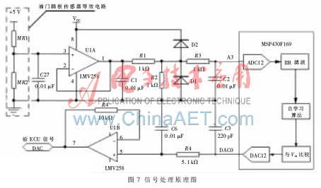
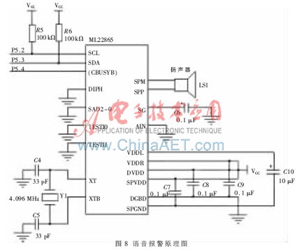
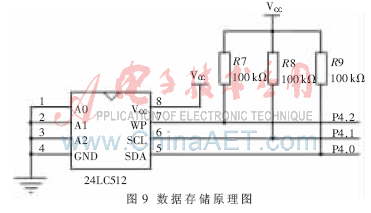
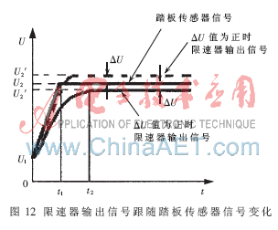
The speed limiter can preset the speed upper limit value Vm through a man-machine interface such as a keyboard and a display. When the speed limiter is activated, the 1 and 3 paths in Figure 2 are connected. The speed limiter detects that the electrical signal transmitted to the pedal sensor is IIR filtered to obtain Ux. Since the speed limiter does not damage the original structure of the car as much as possible, the opening degree of the throttle is used to judge the running speed of the car, but the change of the speed lags behind the change of the throttle, that is, the amount of change of the throttle cannot directly characterize the running speed. The amount of change. Therefore, the speed limiter adopts a self-learning algorithm to monitor the front and rear changes of the throttle and the steady state of the throttle (such as constant speed or stop) in the previous period of time to judge the driver's operation intention and obtain corresponding Travel speed value Vx. Compare Vx with the preset speed upper limit value Vm, if the calculated speed value Vx The electronic throttle system inserted into the speed limiter allows the driver to select whether or not the speed limit function is required. When the driver selects the speed limit function, it works in the same way as the original electronic throttle system without overspeed, maximizing the integrity of the original system. In the design, the contact 1 and the contact 2 in the speed limiter are normally closed switches, so that the speed limiter can ensure the electronic throttle system can still work normally under the condition that the speed limiter can not work normally, and the reliability of the system operation is ensured. In order to meet the above functional requirements, the core of the speed limiter is designed with the powerful MSP430F169 microcontroller, which has a built-in high-speed 12-bit ADC and DAC. It can realize the function of the speed limiter in a single chip without the need to extend the external module. Improve the reliability of system operation, reduce system cost, and meet the functional requirements of the speed limiter. According to the working principle of the accelerator pedal sensor, the principle diagram of the speed limiter signal processing is shown in Figure 7 [2]. The voltage signal output by the pedal sensor is reduced by the operational amplifier to reduce the output impedance, and then input to the ADC input pin A3 of the MSP430F169, and the analog-to-digital conversion is performed by the 12-bit ADC inside the MSP430F169 to realize analog signal acquisition. After the speed limiter collects the electric signal of the pedal sensor, it is filtered by the IIR filtering algorithm. After the self-learning algorithm is calculated and processed, the vehicle traveling speed Vx is obtained and compared with the set speed limit value Vm. The result determines the size of the output of the analog signal output. The output signal is output through the D/A output pin DAC0 of the MSP430F169. The digital-to-analog conversion is realized by the 12-bit DAC inside the MSP430F169, and the driving capability of the output analog signal is boosted by an operational amplifier. (2) The voice alarm unit voice alarm schematic diagram is shown in Figure 8. In order to ensure the safety and stability of the driving, the speed limiter must be started or the speed limiter must be turned off when the car is stopped. Therefore, a voice alarm is provided to effectively remind the user. The speed limiter uses the ML22865 voice chip with power amplifier. The SCL, SDA, and (CBUSYB) pins of the chip are connected to the I/O port P5.2~P5.4 of the MSP430F169, and the SPM and SPP pins of the alarm are connected to the speaker. (3) The data storage principle diagram of the data storage unit speed limiter is shown in Fig. 9. The speed limiter must be able to set the upper speed limit and the large amount of storage space required for the self-learning algorithm, so it must have a data storage function. This design uses 24LC512 memory. (4) Keyboard and display unit Four independent buttons are implemented by P3.4~P3.7 of MSP430F169. The functions are speed limiter open key, value increase key, value decrease key and confirmation key. The display unit uses four 8-segment digital tube displays to display the 4-speed limit value. The display data is provided through the P1 port of the MSP430F169. The P2.0~P2.3 ​​port of MSP430F169 is used as the control port of the digital tube. In order to save energy, the digital tube only lights up when the keyboard is pressed. When the keyboard is no longer operated within 30 s, the digital tube is extinguished. (2) The speed limiter output signal follows the input signal change hysteresis test experiment IIR filtering algorithm and self-learning algorithm will lead to output signal lag and input signal. The MSP430F169 runs at 8 MIPS in this experiment. In order to test the hysteresis effect, the experiment tests its influence by detecting the change of the speed limiter output signal following the pedal sensor signal. The main test items are: the time t1 required for the pedal sensor signal to reach a steady state when the signal of the pedal sensor changes from U1 value to U2 value, and the time t2, t2-t1 difference required for the speed limiter output signal to reach a steady state The value and the steady state state of the two circuit values ​​ΔU are shown in Fig. 12, and the data obtained by the test are shown in Table 2. The experimental results show that the time difference t2-t1 is about 10 ms. The human operation is not felt at this time; the voltage error ΔU is within 3 mV, and the influence of voltage can be ignored. Therefore, time lag and voltage error will not affect the performance of the speed limiter. The car speed limiter described in this paper is flexible to install, does not damage the integrity and reliability of the car, can fundamentally solve the problem of car overspeed, can greatly reduce the vicious traffic accidents, the device is promoted and applied, with the continuous popularization of automobile consumer goods and Consumer safety awareness continues to increase, and car speed limiters will have a broad market in the future.
Shareconn development Co.,Ltd manufacture series audio and video cables, such as HDMI cables, RCA cables, display cables and so on.
Shareconn firmly pursues Excellence in technology innovation and professional service, and strives for more cost-effective, more reliable and higher-speed interconnection solutions. Superlink promises to provide global customers with top quality and the most cost-effective products and services!
Years of hard work lead Shareconn to an excellent international provider, enjoying world-wide prestige of first-class service and customer-orientated philosophy.
Audio Cable Assemblies,Video Cable Assemblies,Automotive Cable Harness Assembly,Electronic Video Cable Assemblies Shareconn Development , http://www.share-conn.com
2 Hardware design of speed limiter<br> From the realization principle of speed limiter, the speed limiter must have the following functions:
(1) Analog signal acquisition, signal processing and signal output speed limiter need to collect the electric signal of the accelerator pedal sensor, so it is necessary to have the analog signal acquisition function, and filter and calculate the collected signal; at the same time, the speed limiter is based on After the signal processing is performed, the corresponding electrical signal is output to the ECU, so an analog signal output function is required.
(2) The control circuit speed limiter needs to realize the functions of the speed limiter working mode, the alarm working mode and the closing mode according to the user's instruction or in some abnormal state. When the speed limiter is in the working mode, it is not only necessary to monitor the accelerator pedal sensor signal, but also to realize the speed limit control according to the pedal sensor signal and the preset speed upper limit value Vm; in the alarm working mode, only the accelerator pedal sensor signal is monitored. In combination with the preset speed upper limit value Vm, an alarm when overspeed is achieved.
(3) The human-computer interaction function speed limiter needs to have the function of human-computer interaction such as display, keyboard and voice alarm output.
According to the above functional requirements, the functional block diagram of the speed limiter is shown in Figure 4. 
The main modules for implementing the speed limiter function are as follows:
(1) Signal Processing Unit The accelerator pedal sensor is actually an angle sensor that extracts the position signal of the instant accelerator pedal and converts it into a voltage signal that is transmitted to the engine controller. Taking the reluctance accelerator pedal sensor as an example, in order to convert the angle change into a voltage signal, the magnetoresistive element is often connected to a three-terminal structure on the same substrate, and a semi-circular magnetic steel is placed at a certain height on the sheet. Its structure is shown in Figure 5. When the main shaft drives the magnetic steel to rotate, the resistance values ​​of the magnetoresistive elements MR1 ​​and MR2 change with the change of the magnetic flux Φ passing through them, so that a voltage signal is output from the midpoints of the two magnetoresistive elements, and the output is processed by the subsequent signal processing circuit. The voltage signal is amplified. By adjusting the amplification factor of the post-amplifier circuit, the required and appropriate voltage signal can be obtained. The equivalent circuit is shown in Figure 6 [1]. 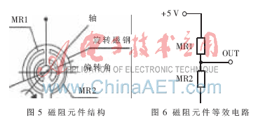
3 Software design of speed limiter<br> The software design flow chart of speed limiter is shown in Figure 10. In order to ensure the safety and stability of the driving, the speed limiter must be started or closed when the car is stopped. The working process of the speed limiter is as follows: the key interrupt program determines whether there is a button for starting or closing the speed limiter. If there is a button signal, the speed limiter determines whether there is an accelerator pedal according to the electric signal of the pedal sensor collected by the main program, if any Press the accelerator pedal, voice alarm, this operation is invalid; if there is no pedal action, remind again whether it is in the driving state, and set the 5 s delay, and press the button again to turn the speed limiter on or off. If it is determined that the speed limiter button is turned off, the speed limiter is turned off, and the off state is set, and the status information is transmitted to the main program; if the speed limiter is activated, the speed limiter is turned on, and the power on state is set, and The status information is passed to the main program. In the main program loop, the pedal sensor signal is first collected and judged by the IIR filter whether there is a pedal action and the information is fed back to the keyboard interrupt program, and then it is judged whether or not the speed upper limit button is set. If so, the corresponding speed value Vm is set and stored in the memory; if not, the electrical signal A/D value Ux of the pedal sensor is read, Ux is derived from the self-learning algorithm to derive the travel speed value Vx. Vx is compared with Vm if Vx 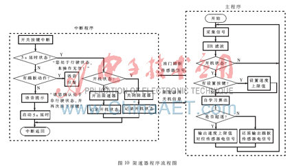
4 Test experiment (1) Speed ​​limiter open instantaneous signal oscillation test experiment In order to detect the reliability of the speed limiter opening instant operation, sample 5 speed limiters to do the experiment and observe the ECU input signal (the signal at the "1" point in Figure 2) ). The main test items are: the time required for the speed limiter to be turned on to stabilize (such as t2-t1 in Figure 11), the maximum amplitude of the instant signal (such as Umax~Umin in Figure 11), and the data obtained by the test are shown in Table 1. Show. The experimental results show that the switching time of the switch is within 1 ms. According to the electrical characteristics of the ECU, the signal interference can be smoothed within 5 ms. The voltage amplitude is also within the range allowed by the ECU, so the switching process is reliable. 


references
[1] Qin Yuwei.Application of Reluctance Angle Sensor in Electronic Throttle System[J].Instrument Technique,2007(4):58.
[2] Wei Xiaolong. MSP430 series single-chip interface technology and system design example [M]. Beijing: Beijing University of Aeronautics and Astronautics Press, 2002.11.