The noise figure (NF) is a commonly used parameter for RF system designers. It is used to characterize the noise of RF amplifiers, mixers, etc., and is widely used as a tool for radio receiver design. The noise figure is described in detail in many excellent communication and receiver design textbooks. This paper focuses on the application of this parameter in data converters.
Many wideband op amps and ADCs are now used in RF applications, and the noise figure of these devices becomes important. Reference 2 discusses the applicable method for determining the noise figure of an operational amplifier. Not only do we have to know the voltage and current noise of the op amp, but we should also know the exact circuit conditions: closed-loop gain, gain-set resistor value, source resistance, bandwidth, and so on. Calculating the noise figure of the ADC is even more challenging, and you will soon understand that this is not true.
When an RF engineer first calculates the noise figure of even the best low-noise high-speed ADC, the result may be relatively higher than the noise figure of a typical RF gain block, low noise amplifier, and so on. In order to interpret the results correctly, you need to understand the position of the ADC in the signal chain. Therefore, be careful when handling the noise figure of the ADC.
ADC noise figure definitionFigure 1 shows the basic model used to define the ADC noise figure. The noise factor F refers to the ratio of the total effective input noise power of the ADC to the noise power caused by the source resistance alone. Due to impedance matching, the square of the voltage noise can be used instead of the noise power. The noise figure NF is the noise factor expressed in dB, NF = 10log10F.
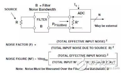
The model assumes that the input to the ADC is from a source with a resistance of R. The input bandwidth is limited to fs/2 and the input has a filter with a noise bandwidth of fs/2. It is also possible to further limit the bandwidth of the input signal, resulting in oversampling and processing gain, which will be discussed later.
The model also assumes that the input impedance of the ADC is equal to the source resistance. Many ADCs have high input impedance, so the termination resistor may be external to the ADC or used in parallel with the internal resistor to produce an equivalent termination resistance of R.
ADC noise figure derivation processFull-scale input power is the power of a sine wave whose peak-to-peak amplitude just fills the ADC input range. The full-scale input sine wave given by the following equation has a peak-to-peak amplitude of 2VO, which corresponds to the peak-to-peak input range of the ADC:
v(t) = Vosin2Ï€ft Equation 1
The full-scale power of the sine wave is:
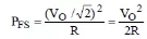
Equation 2
This power is usually expressed in dBm (based on 1 mW):
Equation 3
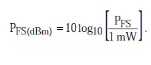
The noise bandwidth B of the filter needs to be further discussed. The noise bandwidth of a non-ideal brick wall filter refers to the bandwidth required for an ideal brick wall filter when the same noise power is passed. Therefore, the noise bandwidth of a filter is always greater than its 3dB bandwidth, and the ratio of the two depends on the sharpness of the filter cut-off region. Figure 2 shows the noise bandwidth of a Butterworth filter with up to 5 poles as a function of 3dB bandwidth. Note: For 2-pole, the noise bandwidth differs from the 3dB bandwidth by 11%; after 2 poles, the two are essentially equal.
The first step in the NF calculation is to calculate its effective input noise based on the SNR of the ADC. The ADC data sheet gives the SNR at different input frequencies, ensuring that the value corresponding to the target IF input frequency is used. Also ensure that the harmonics of the fundamental signal are not included in the SNR value. Some ADC data sheets may confuse SINAD with SNR. Once you know the SNR, you can calculate the equivalent input rms voltage noise from the following equation:
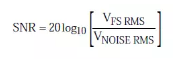
Equation 4
Solved:

Equation 5
This is the total effective input rms noise voltage measured over the entire Nyquist bandwidth (DC to fs/2), note that this noise includes the noise of the source resistance.
The next step is to actually calculate the noise figure. In Figure 3, note that the amount of input voltage noise caused by the source resistance is equal to the source resistance.
The sqrp (4kTBR) voltage noise is divided by 2, which is sqrt (kTBR), because the ADC input termination resistor forms a 2:1 attenuator.
The expression of the noise factor F can be written as:
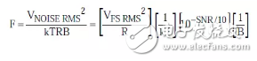
Equation 6
Convert F to dB and simplify to get the noise figure:
NF = 10log10F = PFS(dBm) + 174 dBm – SNR – 10log10B, Equation 7
Where SNR is in dB, B is in Hz, T = 300 K, k = 1.38 &TImes; 10–23 J/K.
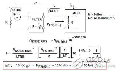
Figure 3: ADC noise figure based on SNR, sample rate, and input power
Where SNR is in dB, bandwidth B is Hz, T=300K, k=1.38 &TImes; 10–23 J/K
Oversampling and digital filtering produce processing gains that reduce the noise figure, as explained above. For oversampling, the signal bandwidth B is below fs/2. Figure 4 shows the correction factor, so the calculation formula for the noise figure becomes:
NF = 10log10F = PFS(dBm) + 174 dBm – SNR – 10 log10[fs/2B] – 10 log10 B. Equation 8
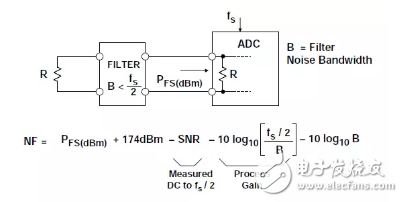
Figure 4: Effect of oversampling and processing gain on ADC noise figure
Calculation example for the 16-bit, 80/100 MSPS ADC AD9446
Figure 5 shows an example of NF calculation for the AD9446 16-bit, 80/105 MSPS ADC. A 52.3 ohm resistor is placed in parallel with the 1 k ohm input impedance of the AD9446, resulting in a net input impedance equal to 50 ohms. The ADC operates under Nyquist conditions and the 82 dB SNR is the basis for the calculation using Equation 8 above, resulting in a noise figure of 30.1 dB.
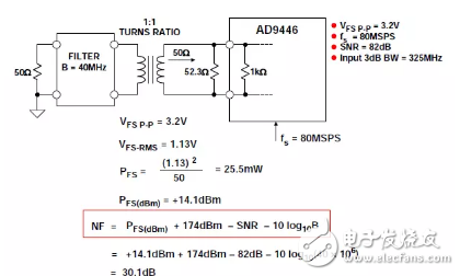
Figure 5: 16-bit 80/100 MSPS ADC AD9446
Example of noise figure calculation for working under Nyquist conditions
Cascaded noise figureIn a typical receiver, the ADC is preceded by at least one low-noise amplifier (LNA) and mixing stage, which provides a sufficiently high signal gain to minimize the effects of the ADC on the overall noise figure of the system.
This can be illustrated by Figure 6, which shows how the Friis equation can be used to calculate the noise factor of the cascaded gain stage. Note that the high gain of the first stage reduces the effect of the second stage noise factor, so the noise factor of the first stage dominates the overall noise figure.
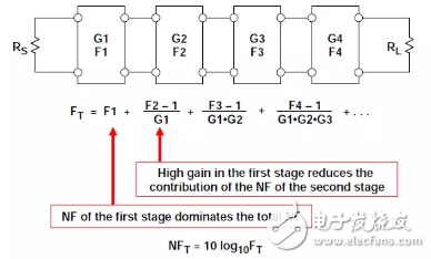
Figure 6: Calculating cascaded noise figure using the Friis equation
Figure 7 shows the effect of a high gain (25 dB) low noise (NF = 4 dB) stage placed before a relatively high NF level (30 dB), which is the typical noise of a high performance ADC. coefficient. The overall noise figure is 7.53 dB, which is only 3.53 dB higher than the first-order noise figure (4 dB).
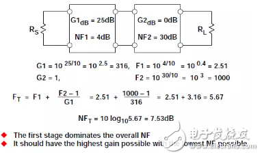
Figure 7: Example of a two-stage cascaded network
ConclusionWhen applying the noise figure concept to characterize wideband ADCs, special care must be taken to prevent misleading results. Trying to reduce the noise figure simply by changing the value in the equation can be counterproductive, resulting in an increase in the overall noise of the circuit.
For example, according to the above equation, NF decreases as the source resistance increases, but increasing the source resistance increases circuit noise. Another example relates to the input bandwidth B of the ADC. According to the equation, increasing B will reduce NF, but this is obviously contradictory, because increasing the ADC input bandwidth actually increases the effective input noise. In the above two examples, the total noise of the circuit is increased, but the NF is lowered. The reason for the decrease in NF is that signal source noise accounts for a large portion of the total noise when the source resistance or bandwidth is increased. However, the total noise remains relatively constant because the noise caused by the ADC is much larger than the source noise.
Therefore, according to the equation, NF is lowered, but the actual circuit noise is increased. In view of this, NF must be handled with care when processing the ADC. Effective results can be obtained using the equations in this paper, but these equations can be misleading if you don't fully understand the noise principles involved. From an isolated perspective, even a low-noise ADC has a relatively higher noise figure than other RF devices such as LNAs or mixers. However, in practical system applications, at least one low noise gain block will be placed in front of the ADC. According to the Friis equation (see Figure 7), it will reduce the total noise contribution of the ADC to a very low level.
Advantages of stainless steel Servo Motor:
1. Reasonable electromagnetic optimization design to reduce reactive power loss
2. Excellent dynamic performance through closed-loop control for real-time control and feedback
3. Compact design, quick installation, wider overspeed range and higher torque output
4. IP65 protection grade, oil and vibration resistance, suitable for a variety of harsh environments and occasions
5. Medium and low inertia, brake, oil seal are optional, support personalized customization
6. High-speed response: No complicated adjustment process is required, which greatly saves debugging time
Stainless Steel Servo Motor,Stainless Steel Servo Motors,Servo Motor Stainless Steel,Servo Motor Stainless Steel Alloy
Kassel Machinery (zhejiang) Co., Ltd. , https://www.kasselservo.com