Embedded systems typically require a digital-to-analog converter (DAC) to generate analog voltages and waveforms. DACs are sometimes used as external devices for embedded processors and sometimes integrated into processors. In either case, the CPU must write the expected output value to the DAC at the appropriate time. In general, we use the timer interrupt CPU to write the expected value to achieve the above purpose. If the DAC must generate a periodic waveform, the CPU must write the next value from the table, increment the table pointer, and check the table boundaries to determine when to reset the data table pointer.
The process of writing a period value to the DAC requires CPU overhead to maintain the output waveform. The CPU overhead required depends on the length of the data table, the frequency of the output waveform, and the operating frequency of the CPU. For example, to generate a 1 kHz sine wave with 32 data points per cycle, the CPU is required to process 32,000 interrupt signals per second at a CPU frequency of 1 MHz. Handling so many interrupts leaves only 1000000 / 32000 = 31.25 CPU instruction cycles between interrupts. For context switching and execution, if each interrupt service only takes 15 CPU cycles, the required CPU overhead will be nearly 50%.
If the application requires a second analog output waveform, the CPU load will increase and the two DACs will not be updated even during the required interrupt service time. The MSP430F15x/16x device is a good solution to this problem. These devices integrate two DACs with one DMA controller. The purpose of the DMA controller is to move data from one location to another without CPU intervention. In this example, the DMA is able to transfer data from the data table to 2 DACs within a specified time.
The DMA controller has three independent channels. Each channel can be used to transfer values ​​between any addresses after configuration. Therefore, a data table can be used for both sine and cosine waves, while two DMA channels only need to access different parts of the data table to form sine and cosine outputs.
In addition, each DMA channel can independently increment its source or destination address. In this example, each DMA channel is incremented by its source address after programming, but the destination address is unchanged and is always its corresponding DAC data register.
The number of DMA transfers can also be configured. After each DMA channel has transferred the programmed data value, the next transfer can be started from the originally programmed source address, so that each DMA channel forms a ring buffer with a data table and generates a periodic waveform.
To move data values, a trigger is required for each DMA channel. In this example, the interrupt flag from each DAC is used as a trigger for its corresponding DMA channel. If two channels are triggered at the same time, the DMA channel needs to be prioritized, which causes a delay in one of the DACs that receive the data, which in turn causes the output signal to be distorted, so the DAC update should be handled separately.
Loaded into the DAC data register, each DAC can output a new value when the timer triggers the DAC. In this example, each DAC is triggered by the TImer_A1 output signal. Since the two DACs use the same trigger signal, the output waveforms of each DAC are synchronized with each other to maintain the corresponding sine/cosine relationship.
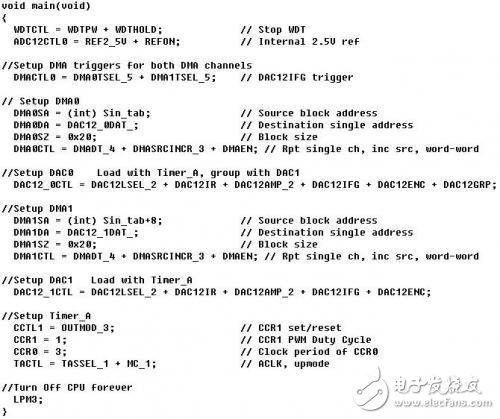
The oscilloscope screen for the complete code and 2 output waveforms is listed below.
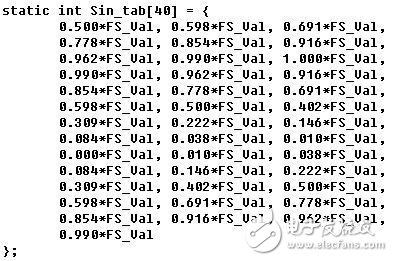
#define FS_Val 4095
Finally, each DMA transfer is forced to occupy 2 CPU clock cycles. Although the CPU is not used for transfer operations, the clock cycle is used to cause the necessary CPU overhead and is greater than zero. However, for a 1 kHz sine wave, assuming 32 data points, 2 cycles beyond the 31.25 data points require only 6.4% overhead, compared to nearly 50% when not using DMA. In addition, generating 2 waveforms requires only 4 cycles or 7.8% overhead, and it is almost impossible to generate 2 1 kHz sine waves without using DMA.
Table Air Purifier,Table Top Air Purifiers,Table Top Air Filter,Tabletop Hepa Filter
CIXI KYFEN ELECTRONICS CO.,LTD, , https://www.kyfengroup.com