You think your RF (RF) sampling design works fine because you have chosen the right device and defined the clock source. But wait a second; what you have to do is far from it. Even the best devices can cause performance degradation without proper frequency planning to ensure that a clean spectrum is produced in harmonics or clock mixing spurs. Frequency planning is always part of a good transceiver design, but RF sampling is more critical because the signal is always in the desired frequency band. Unlike other configurations with intermediate frequency (IF) or base frequency (BB), the RF sampling architecture does not have narrowband channel filtering for clean spectrum.
In these transmitters, the management requirement will strictly limit the level of the spurious product to fall within the desired frequency band and just outside the band. The stray product generated within these converters cannot be effectively filtered out before reaching the power amplifier (PA). Once exposed to radiation, these products can interfere with other users.
Frequency planning with an RF sampling digital-to-analog converter (DAC) ensures that the harmonic content in the first Nyquist region of the fold back is not within or near the desired frequency band. The frequency band for the specified application is fixed; it is not adjustable, but you can adjust the sample rate of the converter. Increasing the sampling rate produces a larger Nyquist zone; however, this does not guarantee an optimal solution.
Transmitter frequency planning exampleLet's look at an example of a transmitter that runs at 2.14 GHz and has a signal width of 60 MHz. Figure 1 shows the first Nyquist zone spectrum with a high frequency clock rate of 8024 MHz. At this rate, the required frequency band (marked in blue) is clear, but the third and fourth order harmonics, as well as the known spurs (marked in yellow), are located near the desired frequency band. These stray products are difficult to filter out.
Figure 1b shows the same frequency, but the clock rate is reduced to 5683.2 MHz. At this clock rate, higher order harmonics or clock mixing spurs are not located near the desired frequency band. In this example, the lower sample rate method is more appropriate because you can easily filter out high-order spurs.
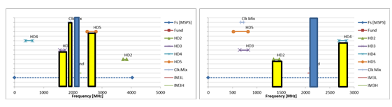
Figure 1: Spectrogram at clock frequencies of 8024MHz (a) and 5683.2MHz (b)
Receiver frequency planning exampleThe frequency planning goals are slightly different for the receiver. Interference from in-band and out-of-band signals can seriously affect the sensitivity of the receiver. By performing appropriate band-limited filtering on the RF input, you can minimize the out-of-band sources of interference caused by other user signals or transmitter interference. You cannot filter out in-band interference sources. Frequency planning ensures that the harmonic content from the in-band interferer does not fold back into the interior of the desired band. Unlike the case of the transmitter, it is not a problem to just fold the harmonic content outside the return band.
Figure 2 shows a 100MHz wide signal operating in the band with a center frequency of 1950MHz. The clock frequency is 6144MHz. In this configuration, all of these higher order harmonics are outside the band. The second and fourth harmonics are very close, but not inside the band. This is unmatched by a traditional low IF architecture. A lower sample rate analog-to-digital converter (ADC) operating with the same signal bandwidth cannot achieve a clean spectrum because the foldback harmonics cover the entire Nyquist zone.
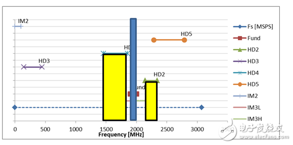
Figure 2: Spectrogram with a clock frequency of 6144MHz and a bandwidth of 100MHz in the central frequency range of 1950MHz
You can modify the clock frequency to maintain a clean spectrum when the desired frequency changes. When using a traditional architecture, adjustments to the frequency plan require you to modify the synthesizer and IF or baseband filter stages. Simply adjust the sampling rate and the RF sampling architecture enables simple frequency planning adjustments. Since the operation of the different frequency bands only requires adjustment of the clock frequency, the RF sampling architecture can be easily adapted to the requirements of different frequency bands and applications.
Next month, I will discuss the timing requirements for RF sampling ADCs. Please leave us a message below and tell us what you would like to know about the RF Sampling Converter design.
Like most of the heat shrinkable tube, a temperature shrinkage performance, its characteristic is different on the surface after especially after processing, the surface mesh structure pattern, color a lot of kinds, certainly valuable ornaments, overseas has been widely used
The key is used in: rod, fitness equipment, hardware tools, sedan, motorcycle, bicycle, ship, textile equipment, garden Landscape equipment also has all kinds of rocker decoration design, decoration design of comfortable beautiful atmosphere, anti-corrosion and anti-cooling, convenient installation, labor and time saving.
Heat Shrink Tube Textured (or Textured Heat Shrink) is made of polyolefin material modified by irradiation.
Electrical Heat Shrink Tubing mainly used in sports equipment, fitness equipment, high-grade fishing tackle, daily necessities, all kinds of tools, kitchen utensils handle anti-slip decoration and other fields.
We are the professional manufacturer of Rigid Heat Shrink Tubing in China for more than 25 years,if you want to know more information about our company and products, please visit our website.
Heat Shrink Tube Textured,Textured Heat Shrink,Textured Shrink Wrap,Electrical Heat Shrink Tubing
CAS Applied Chemistry Materials Co.,Ltd. , https://www.casac1997.com