Based on the analysis of real-time embedded system mC/OS-II and LPC2119 chips, this paper analyzes and discusses the knowledge and needs of mC/OS-II before migration to the processor. The specific work of the transplant. The paper focuses on the transplantation of mC/OS-II.
μC/OS-II is a complete, portable, curable, and scalable preemptive real-time multitasking kernel. It is powerful and supports 56 user tasks. It supports many common processes such as semaphores, mailboxes, and message queues. Inter-communication mechanism. Open source code, the program is readable, portable, and freely available.
The LPC2119 is a 32-bit ARM7TDMI-S microprocessor manufactured by PHILIPS. Its core is a high-performance 32-bit RISC architecture with a high-density 16-bit instruction set and extremely low power consumption. With zero-waiting 128K bytes of on-chip FLASH and 16K of SRAM, there is no need to expand the memory, making the system simpler and more reliable.
Table 1
This paper mainly discusses the transplantation of μC/OS-II on LPC2119, and analyzes the basic knowledge that needs to be mastered before transplantation. In particular, it analyzes the three documents closely related to transplantation and also analyzes the used chips. The remapping concept is described in detail.
Introduction to LPC2119In addition to the memory described above, the LPC2119 on-chip resources include two UARTs, a high-speed I2C interface, two SPI interfaces, six output PWM units, four 10-bit AD converters, two 32-bit timers, and two CANs. Channels, real-time clocks, and watchdogs can achieve a CPU operating frequency of up to 60MHz with an on-chip PLL.
Since the following startup code is written using the concept of remap, the LPC2119 and other series of chips such as AT91 also have the function of re-mapping, so the description here is useful for learning other ARM chips.
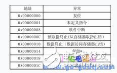
In the memory of the ARM chip, the exception vector table is shown in Table 1.
When the system is powered on, the program will automatically start from the 0 address, so in the initial state of the system, the memory at the 0 address is required to be non-volatile ROM or Flash. However, the access speed of ROM or Flash is relatively slow. After each interrupt occurs, it starts from reading the vector table on ROM or Flash, which affects the interrupt response speed. Therefore, LPC2119 provides a flexible address remapping method that remaps the address of the internal RAM to the location of 0x0. Before the system executes the remapping command, the interrupt vector code in Flash needs to be copied to the internal RAM. This is equivalent to finding the interrupt vector from the 0x0 position in the internal RAM after the remapping command is executed, but actually mapping the starting address 0x40000000 of the RAM to 0x0. In this way, when the interrupt is executed, it is equivalent to finding the corresponding interrupt vector in the RAM to implement exception processing debugging.
Introduction to μC/OS-II
μC/OS-II is actually an embedded operating system kernel. The basic service provided by the kernel is task switching. In μC/OS-II, a dedicated stack space is allocated for each task. When μC/OS-II performs task switching, the CPU register of the current task is placed on the stack of this task, and then the original working register is restored from the stack of another task, and another task is continued. Therefore, the stacking and popping of registers is the basis of μC/OS-II multitasking scheduling.
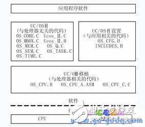
Figure 1 μC/OS-II hardware and software architecture
The structure of μC/OS-II is shown in Figure 1.
As shown in Figure 1, the code associated with the processor has only three files. Generally, you only need to modify these three files when you migrate.
Write startup code
The startup code is a piece of code that is executed before the main () function of the C language after the chip reset, and is mainly to provide a basic operating environment for running the C language program, such as initializing peripheral components, memory systems, and the like. Therefore, the function of starting the code is somewhat similar to the BIOS in the PC and the Bootloader in VxWorks. Since Philips does not provide the boot code for this chip, you will need to write your own startup code.
The startup code can be divided into five files: STartup.s, IRQ.s, stack.s, heap.s, and target.c. Startup.s contains the exception vector table and system initialization code mentioned above, generally no need to change; IRQ.s contains the interface code of the interrupt service program and C program, which can be modified according to the actual interrupt situation; stack.s and The heap.s saves the start position of the heap and stack used by the C language; target.c contains the special code of the target board, including the exception handler and the target board initialization program, which can be modified according to the needs of the program.
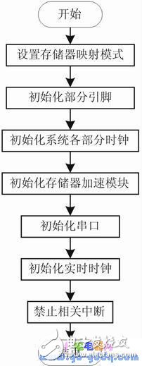
Figure 2 System basic initialization Tar get Peset1 ni t () flow chart
Because the startup code is written very long, and this article just wants to point out that writing the startup code is a preparation that must be done before the migration and a brief description of it, so not all the code is listed here (see the reference for the specific startup code [ 1]), and give a very important flowchart of the target TargetReseTInit() in the target board initialization program, from which you can see the specific steps of the basic initialization of the system before entering the main () function.
Copper Lugs,Copper Cable Lugs,Plating Copper Cable Lugs,Copper Tube Terminal Lugs
Taixing Longyi Terminals Co.,Ltd. , https://www.longyicopperterminals.com