How to increase the bandwidth of digital potentiometer from 10 times to 100 times
This article introduces a simple circuit that can increase the bandwidth of a digital potentiometer from 10 times to 100 times. Using this method, digital potentiometers can be used for high-frequency applications of video bandwidth.
Digital potentiometers (digital pot or digipot) are widely used to control or adjust circuit parameters. Generally speaking, due to the bandwidth limitation of the digital potentiometer, it can only be used for DC or low frequency applications. Its typical -3dB bandwidth is within 100kHz to several MHz, depending on the model. However, by using the simple method described below, the signal bandwidth of the potentiometer can be increased from 10 times to 100 times, and a 0.1dB bandwidth of 4MHz and a -3dB bandwidth of more than 25MHz can be obtained. Using this method, digital potentiometers can be used for video or other high-speed applications.
This method takes advantage of the fact that in many digital potentiometer applications, the potentiometer is used to fine-tune the signal and does not require full-scale adjustment from 0% to 100%, such as: one-time factory calibration. In these examples, the digital potentiometer generally provides an adjustment range of less than 10%. We use this limited adjustment range to increase the bandwidth of the digital potentiometer.
Typical potentiometer circuit configuration is shown in Figure 1. Here, the digital potentiometer is used to change the attenuation of the signal. R2 is a digital potentiometer, and the parasitic capacitance (Cwiper) is also marked in the figure. This capacitance is inherent in all digital potentiometers, which limits the circuit bandwidth. When the potentiometer swings between 0 and full scale, R1 and R3 are used to limit the signal attenuation caused by the digital potentiometer. 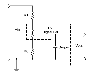
Figure 1. Typical digital potentiometer circuit configuration
Note: Because of the operational amplifier, this circuit can be used for amplification and attenuation. Of course, the method of increasing bandwidth described below has nothing to do with the selected circuit topology.
To calculate the circuit's transfer function (VOUT / VIN), different modes of potentiometers can be used—see Figure 2. In the figure, R2 is divided into R2top and R2bottom, where R2top is the resistance above the potentiometer contact and R2bottom is the resistance below the potentiometer contact. Assuming that the potentiometer we use has an end-to-end resistance of 10kΩ (ignoring the effect of contact resistance), the ideal transfer function of R2top and R2bottom with respect to digital coding is shown in Figure 3. The two endpoints and midpoint of the transfer function are described below:
(2) When the potentiometer code = middle position, R2top = R2bottom = 5kΩ
(3) When the potentiometer code = full scale position, R2top = 0kΩ, R2bottom = 10kΩ
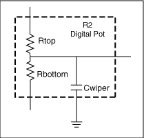
Figure 2. Digital potentiometer, R2 is divided into R2top and R2bottom 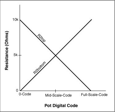
Figure 3. Ideal transfer function of a digital potentiometer
From Figure 4 we can derive the DC transfer function of VOUT / VIN:
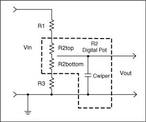
Figure 4. Circuit configuration of a typical digital potentiometer. The digital potentiometer uses a new model
Below, let us make some assumptions:
Assuming R2 = 10kΩ (the commonly used digital potentiometer resistance value), if you want to attenuate the input signal to any level, for example, 70% ± 5% of the input value (65% to 75% of the input value).
Then, using equations (1) – (4), you can see that there is an adjustment range of 65% to 75%, and the nominal value (middle position) is 70%:
Using the resistance value of equation (5), assuming Cwiper = 10pF, the bandwidth listed in Table 1 can be obtained. The actual contact capacitance is in the range of 3pF to 80pF, which is related to the contact resistance, the number of steps, the IC process used, and the potentiometer architecture. Typical capacitance values ​​for 10kΩ potentiometers with 3V to 5V supply and 32 to 256 steps are 3pF–10pF.
Note that this analysis is based on the assumption that the contact capacitance is in parallel with the potentiometer resistance, thereby limiting the bandwidth of the potentiometer. This method is the most direct way to use the potentiometer. If a more complicated potentiometer configuration is used, the bandwidth may be further limited. Therefore, the following discussion on increasing bandwidth is very useful, even if the actual bandwidth does not achieve the intended purpose.
Table 1. Bandwidth of the circuit in Figure 1, using Equation 5 resistors
| CondiTIon | Cwiper = 10pF * | ||
| -0.1dB bandwidth | -0.5dB bandwidth | -3dB Bandwidth | |
| Pot at 0 Code | 106kHz | 245kHz | 702kHz |
| Pot at Mid Scale | 115kHz | 265kHz | 760kHz |
| Pot at Full Scale | 130kHz | 296kHz | 852kHz |
For applications such as video, these bandwidths are still too low.
Improve circuit bandwidth using low resistance potentiometer
One of the most obvious ways to increase the circuit bandwidth is to choose a digital potentiometer with a lower resistance value, for example, a 1kΩ potentiometer, and adjust R1 and R2 proportionally. ). However, low-resistance digital potentiometers (1kΩ) generally occupy a larger die area, which means higher cost and larger package size. For this reason, the practical application of 1kΩ potentiometers is very limited.
If a potentiometer can meet the design requirements, the bandwidth of the 10kΩ potentiometer mentioned above will increase linearly as the resistance decreases, for example, by 10 times (assuming that the capacitance of the stray contact does not change).
For example, using a 1kΩ potentiometer, setting R1 = 2.49kΩ, R3 = 6.49kΩ, the contact capacitance is 10pF, and the potentiometer is set in the middle position, you can get -0.1dB bandwidth of 1.15MHz, and -3dB bandwidth of 7.6MHz. This is 10 times higher than the bandwidth listed in Table 1.
Compared to 1kΩ potentiometers, choosing 5kΩ and 10kΩ potentiometers may be a better solution-you can get potentiometers in smaller packages, from which you can choose volatile or non-volatile memory, and more digital interface options (up / down, I²C, SPI ™) and adjustment steps (32, 64, 128, 256, etc.). For this reason, the following design example selects a potentiometer with an end-to-end resistance of 10kΩ.
Assuming that due to cost, volume, interface, and adjustment steps of the potentiometer, it is necessary to use a 10kΩ end-to-end resistance potentiometer. In this case, how to increase the bandwidth of the circuit in Figure 1?
One way to increase the bandwidth is to remove the resistors R1 and R3 and use a potentiometer with more steps than the circuit in Figure 1. For example, a 32-step potentiometer obtains a 10% adjustment range. According to the above introduction, you can choose to replace this one-step potentiometer, and use a 256-step potentiometer to remove R4 and R6, limiting the adjustment range of the potentiometer to meet the requirements Within the decay code—we continue with the design goals above, 65% to 75%. This method is explained in Figure 5. The encoding used is from 0.65 × 256 (= 166.4, use 166) to encoding 0.75 × 256 (= 192). In this example, a 256-step potentiometer is used; due to the limited coding, the number of available steps is limited to 26 (ie, a 10% adjustment range, only 10% of the 256 steps are used). The 26-step usable range corresponds to the 32-step range in the above example. 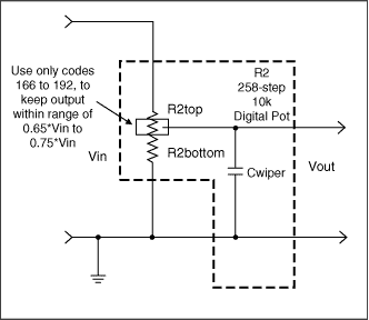
Figure 5. Partial coding using only high-precision (256-step) potentiometers to obtain an adjustment range of 0.65 to 0.75
Compared with the 32-step potentiometer, a disadvantage of this method is that the cost of the 256-step potentiometer is much higher, and the potentiometer package size that can be selected is larger (extra precision requires additional switches-for example, Compared with 32 steps, 256 steps need to occupy additional die area, and these switches are not conducive to improving Cwiper). Assuming that Cwiper is 30pF, VOUT / VIN = 0.70—at the midpoint of the adjustment range, the circuit in Figure 5 has a -0.1dB bandwidth of 384kHz, -0.5dB bandwidth of 879kHz, and -3dB bandwidth of 2.52MHz. Compared with the results in Table 1, the bandwidth is increased by 3 times.
A lower cost and better performance solution is to add some discrete resistors to the circuit in Figure 1, as shown in Figure 6. 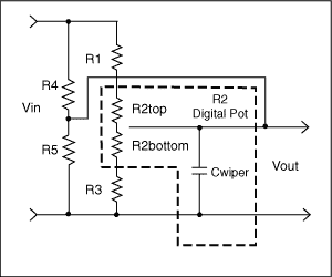
Figure 6. Using two parallel resistors (R4 and R5) in the original circuit, the bandwidth is increased by a factor of 100 compared to Figures 1 and 2.
The circuit in Figure 6 adds a parallel resistance to Figure 1 (note that the digital potentiometer model introduced in Figure 2 is used). The parallel resistance reduces the circuit impedance (thereby increasing the bandwidth). By setting the circuit gain, limiting the attenuation caused by the digital potentiometer swinging from 0-code to full-scale code can achieve a dual purpose.
Setting the gain of the potentiometer circuit, using parallel devices to limit its adjustment range (R4 and R5, rather than simply using series devices R1, R2 and R3), the circuit bandwidth is better than the bandwidth of Figure 1.
Also note that resistors R1, R2, and R3 also affect the circuit gain, but since their series resistance is much larger than R4 and R5, this effect is very small.
A few simple examples can illustrate the impact of R4 and R5 on the circuit in Figure 6. In Figure 7, the resistance in the upper part of the circuit adopts the resistance combination value given by the equation in the figure. Note that because R4 is in parallel with R1 and R2top, it reduces the circuit impedance. 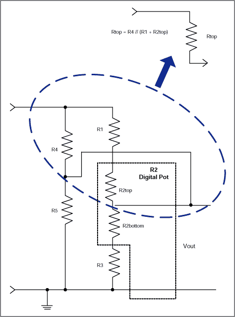
Figure 7. Simplified circuit "upper" resistance
In Fig. 8, the resistance of the lower part of the circuit adopts the resistance combination value given by the equation in the figure. Note that because R5 is in parallel with R3 and R2bottom, it also reduces the circuit impedance. It is the lower circuit impedance that makes the bandwidth significantly higher and meets the design goals. 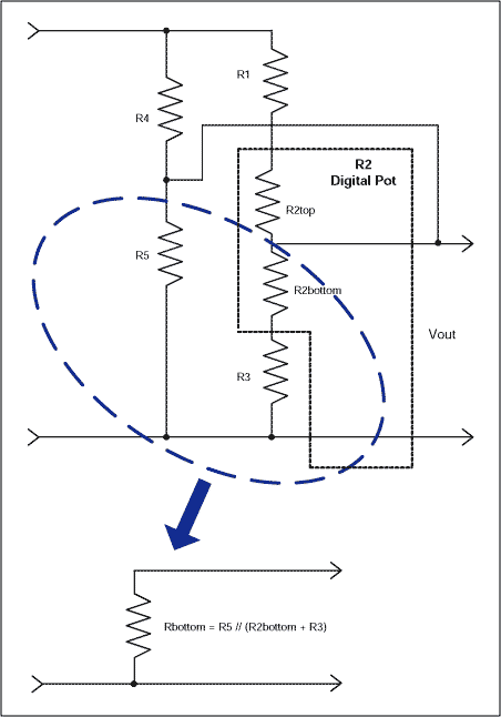
Figure 8. Simplified circuit "lower" resistance
Figure 9 combines the simplified example in the previous figure and shows the VOUT / VIN transfer function. It can be clearly seen from the figure that by reducing the circuit impedance (Rtop is less than R1 + R2top, Rbottom is less than R2bottom + R3), the circuit bandwidth is increased. 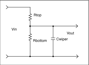
Figure 9. Simplified circuits of Figures 7 and 8
Actually setting the resistance of R1, R3, R4 and R5, you can compare the bandwidth obtained by the circuit in Figure 1 to determine the impact of R4 and R5 on the performance of the circuit.
Using the equation in Figure 9, the resistance of R1, R3, R4, and R5 can be derived, and then the final bandwidth can be calculated.
Using the table, you can find the component values ​​that satisfy the equation in Figure 9:
Using these components is worth the bandwidth listed in Table 2. Note that these results are 100 times better than the circuit in Figure 1, the data is listed in Table 1 !!
Table 2. Bandwidth of the circuit in Figure 6, using Equation 6 resistors
| CondiTIon | Cwiper = 10pF * | ||
| -0.1dB bandwidth | -0.5dB bandwidth | -3dB Bandwidth | |
| Pot at 0 Code | 4.1MHz | 9.3MHz | 26.3MHz |
| Pot at Mid Scale | 4MHz | 8.9MHz | 25.1MHz |
| Pot at Full Scale | 4.3MHz | 9.6MHz | 27.3MHz |
to sum up
This article introduces the method of simply adding a few parallel resistors in a narrow-band digital potentiometer to increase the system bandwidth, which can significantly improve system performance (bandwidth can be increased by 100 times). The design premise is to assume that the actual application allows reducing the control range of the potentiometer to increase the bandwidth. After the bandwidth is increased, the digital potentiometer can be used in the high-frequency field that could not be previously involved, such as video signal link control.
Switch Mode Power Supply include Plug Type Power Supply,Desktop Type Power Adapter,Network Power Supply and 4 Spliters DC Power Supply etc. Switching power supply exclusive Patent : 12v dc power supply Multi-function power plug, it is changeable plug.Plastic housing use ultrasonic process, it is No need any screw.100% Enough Power, High efficiency, all above 80%.
Features:
Wide input range: 100-240V, 50/60Hz.
Exclusive Patent : Multi-function power plug,changeable plug.
Protections:short circuit, over current, overload,over voltage.
Being available for direct plug-in type,desktop type, wall-mounted type.
Customized Ac Plug , EU,UK,USA,AU Plug is available
100% full load burn-in test
Output voltage between 12VDC and 24VAC that can satisfy the demands for various types of power
Adopts No hole design, Plastic housing use ultrasonic process, it is No need any screw.
3 years warranty
Product application:
Application to CCTV System, Access control System, Alarm System.
Switch Mode Power Supply
Switch Mode Power Supply,Switch Mode Power Supply Design,Switch Mode Power Supply Schematic,Switch Mode Power Supply Advantages
Guangdong Steady Technology Co.LTD , https://www.steadysmps.com