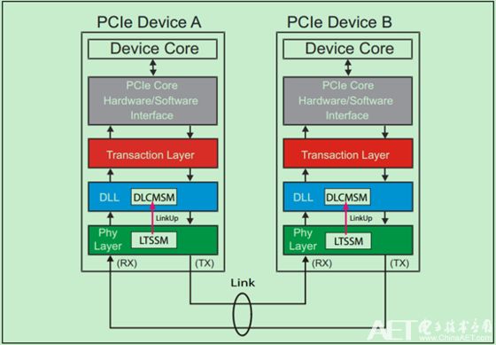
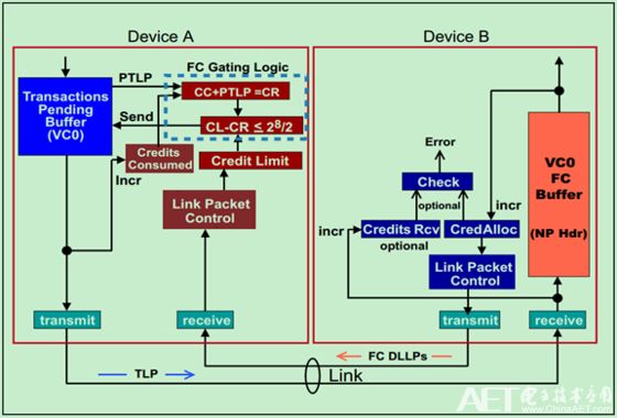
The PCIe bus must complete Flow Control initialization before any Transaction Layer Packets (TLPs) are sent. After the physical layer completes the link initialization, the LinkUp signal will become valid, telling the data link layer to start Flow Control initialization.
As shown below:
Note: Since VC0 is enabled by default, when the Flow Control initialization starts, it will be automatically initialized. Other Virtual Channels are optional and will only be initialized when they are configured to enable.
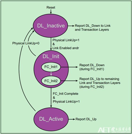
Flow Control initialization is divided into two steps, FC_Init1 and FC_Init2, which are located in the entire Data Link Control & Management State Machine as shown below:
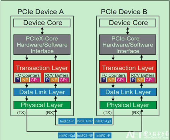
In the FC_Init1 step, the PCIe device continuously sends three InitFC1 Flow Control DLLPs to report the size of the receive buffer. The order of the three DLLPs is fixed: Posted, Non-Posted, and then Completions. As shown below:
FC_Init2 is similar to FC-Init1. It also sends three InitFC2 type DLLPs. When completed, DLCMSM (the state machine mentioned in the previous article) will switch to DL_Active state, indicating that the data link layer initialization is complete.
Note: Some people may have doubts, FC_Init1 and FC_Init2 are not doing nearly the same thing. Why do you need FC_Init2? The reason is that different devices may have different FC_Init1 time. FC_Init2 is added to ensure that each device can receive FC initialization DLLP.
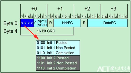
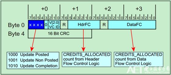
FC_Init DLLP format as shown below:
After the FC initialization is completed, the size of the receive buffer is updated periodically between the adjacent two devices through the Updated FC DLLP. As shown below:
The format of Update FC DLLP is similar to that of FC_Init, as follows:
Said earlier. Update FC DLLP is sent periodically, and the period value can be calculated by the following formula:

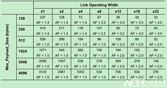
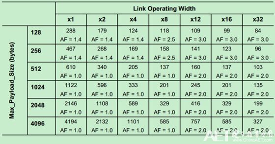
Specific reference can be made to the Spec of PCIe, which will not be described in detail here. The periodic table of Gen1 and Gen2 is given below (the result calculated according to the formula). Among them, AF is AckFactor.
Note: Mindshare's book, in order to facilitate understanding, to modify the word AckFactor UpdateFactor, actually refers to the same thing.
Gen1 (2.5GT/s) is shown in the following table:
Gen2(5GT/s) is shown in the following table:
20 Awg Tinned Copper Wire,Tinned Copper Conductor,Stranded Tinned Copper Wire,Tinned Copper Wire Price
Sowell Electric CO., LTD. , https://www.sowellsolar.com