With the increasing speed of modernization, the development of motor vehicles and drivers has brought unprecedentedly higher requirements to the traffic management department. In order to put the first pass of good traffic safety, deliver qualified drivers to the society, and better serve economic construction, research and develop a scientific and reliable computer road test system to conduct road driving and venue tests for motor vehicle drivers, and become The common focus of the computer application R & D unit. The vehicle-mounted communication system is a very important part of the road test system. It is related to the normal operation and display of the entire system. It is the bridge and link between the various systems. After it accurately detects and locates the driver and the test vehicle in the full driving situation through the on-board equipment, the on-board communication system transmits the data obtained in the test process in the form of digital information to the main control testing center through the wireless network, and passes the monitoring equipment and The management software monitors and manages the entire examination situation in a timely manner, and then implements a unified network management system for all examination situations through the network. Therefore, the development and research of vehicle communication systems are particularly important.
1 Requirements for in-vehicle communication system In-vehicle communication system needs to monitor the vehicle status information from various sensors during the work process, and the purpose of monitoring this information is to understand the working status of the vehicle, so as to make corresponding processing. Therefore, the vehicle communication system should meet the following two basic requirements:
(1) High real-time performance Generally, the starting time of the test car is no more than 3s, and the shift time is shorter during the test. It is usually completed in about 1s, the steering wheel swing can be completed in about 1-2s, and the control cycle is within 50ms. To truly reflect the "micro" working process of the system, the data collection and update cycle of the vehicle communication system should also be within 50ms.
(2) A large amount of information The vehicle-mounted communication system needs comprehensive monitoring of the engine, clutch and transmission during its work. It needs to collect various vehicle status information through sensors, including: door signal, seat belt signal, handbrake signal, reverse Signal, clutch signal, main brake signal, auxiliary brake signal, throttle signal, gear signal, engine speed signal (start), mileage (speed) signal, car direction signal, vibration signal, car swing signal, etc. Although the amount of data collected each time is not much, in order to fully reflect the working state of the system, it is necessary to store and analyze the signal information; and the previous analysis knows that the data update cycle is short, so the total amount of information is large.
2 Overall design plan of vehicle communication system
2.1 The system hardware structure design takes into account the requirements for the application of the vehicle communication system, using PC104 components as the core component of the vehicle communication system, as the upper computer; It is connected through Siemens PC / PPI communication cable protocol converter; the system uses wireless LAN to communicate with the monitoring center and base station; the video server is used to capture the image information during the cab test and convert it into digital image information on the network , Transmitted on the local area network, so that the test monitoring center can monitor the entire test process and record the test screen information; GPS is the landmark positioning (detection, calibration project location and driving track); the fingerprint device is used to identify the identity of the candidate and examiner; the sensor is The signal required by the detection system reflects the working state. In the process of signal transmission, interference should be considered. The sensor signal is transmitted to PLC or PC104. The hardware structure of the entire system is shown in Figure 1.

2.2 System function decomposition According to the hardware structure of the system, the functions of the system can be divided into two parts: data collection, processing and data transmission of the lower computer; data reception, processing, display and wireless communication of the data of the upper computer. Specifically, the main functions of the lower computer include: collecting vehicle sensor signals, monitoring sensor signal status, and outputting logic judgment codes according to examination rules; receiving PC104 instructions to complete the collection and judgment process. The main functions of the PC104 component of the host computer are: collecting and analyzing site project signals and GPS signals; as the host computer, managing the PLC work, receiving the data transmitted by the lower position and making corresponding processing; intelligent analysis of the information of candidates and examiners and examination results Judgment; Examiner information of candidates, local archive of test results and real-time upload; management of voice and data communication; real-time dynamic display of process information, etc. 2.3 Connection of PC104 and PLC The serial port of PC104 is RS232 interface, and Siemens S7-200 free port is RS485 communication port. Therefore, the dedicated PC / PPI programming cable of Siemens is used as the connection cable of the host computer. It realizes the conversion of RS232 and RS485, and has the function of isolation and anti-interference. The connection diagram between the two is shown in Figure 2. 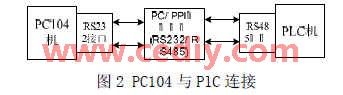
3 Software development of vehicle communication system
3.1 Software development of lower computer
3.1.1 PLC serial port initial setting
The communication port on the S7-200 CPU works in free port mode is a serial communication function based on RS-485 half-duplex hardware. In free port mode, the communication protocol is completely controlled by the user ladder program. SMB30 is used to select the bit rate and check type. The bits and meanings of SMB30 are as follows: 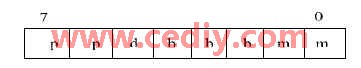
pp, check method: 00 and 11 are no check, 01 is even check, 10 is odd check;
d, character length: 0 is the effective data of the transmitted character is 8 bits, 1 is the effective data is 7 bits;
bbb, baud rate: 000 is 38400baud, 001 is 19200baud, 010 is 9600baud, 011 is 4800baud,
100 is 2400baud, 101 is 1200baud, 110 is 600baud, 111 is 300baud;
mm, communication protocol: 00 is the PPI protocol slave mode, 01 is the free port mode, 10 is the PPI protocol master mode,
11 For reservation, the default setting is PPI protocol slave mode.
This article uses no parity, 8 data valid bits, baud rate 9600baud, free port communication.
3.1.2 Freeport communication protocol format (1) Data direction: PC104 to PLC 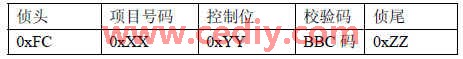
Note:
0xXX: number range 0x01 ~ 0x0C (12 sub-items);
0xYY: start 0xAA; stop 0x00;
0xZZ: 0xFD (end character);
BBC check code: the XOR sum of the project number and the number of control data bytes.
(2) Data direction: PLC to PC104
Data format: hexadecimal 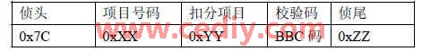
Note:
0xXX: number range 0x01 ~ 0x0C (12 sub-items);
0xYY: User-defined evaluation standard (self-coding);
0xZZ: 0xFF (end character);
BBC check code: XOR sum of the project number and the number of deducted project data bytes.
3.1.3 PLC programming
The PLC selects the free port communication mode. The command XMT and the receive command RCV are sent through the free port, or the character interruption is combined with a custom communication protocol programming program to control the operation of the communication port. The communication parameters are configured by the bits of the special register SMB30. The S7-200 PLC first executes the initialization subroutine during the first scan to initialize the RCV instruction of the port. After the initialization is complete, run the RCV instruction to make the port in the receiving state. The PLC will send a feedback message for each instruction received. After the feedback information is sent, an interrupt will be generated. Due to space limitations, the entire program only draws the PLC program block diagram shown in Figure 3. 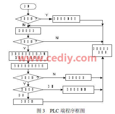
Among them, the initialization subroutine mainly completes the setting of the communication port, the definition of the start character and the end character, the setting of the high-speed counter, and the initialization of the receiving and sending interrupts. The verification and analysis subprogram mainly completes the verification and analysis of the received instructions to determine the number of each test subitem in order to start the corresponding item subprogram. The project subroutine starts the corresponding subproject program according to the instruction, and completes the judgment and processing of various sensor signals of the project.
3.2 PC software development The core of the PC control program is human-computer interaction, serial data acquisition, processing, display and remote data communication (communication between the control center and the site base station). Therefore, in the process of compiling the PC server program, the operating system of the server adopts the operating system familiar to users, such as Windows XP, etc., and uses VC advanced programming language to develop application programs. The object-oriented method is used to develop the host computer software. The main use cases are data acquisition, processing, transmission and display.
(1) The data collection system needs to collect GPS serial data and sensor group signals during the work process. GPS data is landmark positioning, which is mainly used to detect and calibrate the project location and driving trajectory, determine whether the driving enters a certain test project, so as to record the entire test situation of the project. Collecting sensor group signals includes the sensor signals in the car and the sensor signals of the base station. In order to reflect the basic working state of the test car, these sensor signals are processed accordingly.
In serial data collection, the data received by the host computer is often asynchronous and bursty. Introducing multithreading in the acquisition module program, that is, creating a special communication thread to access the serial port, this method can effectively overcome the stagnation and unresponsive phenomenon in serial communication. The specific implementation of this paper is composed of the main thread of interface interaction and the background auxiliary thread that processes the serial port. The main thread is responsible for data collection, used to initialize the serial port, customize communication event messages, create and delete auxiliary threads and coordinate the operation of each thread. The background auxiliary thread is the core of serial port data collection, including three threads: serial port monitoring thread, receiving thread and data processing thread. The monitoring thread performs real-time monitoring of the serial port in the background. When a predefined message is monitored, the receiving thread is immediately called to automatically receive data and trigger the data processing thread. After the data processing thread processes the data, the main thread is notified to save the processed data, and then continue to The serial port is used for monitoring, which ensures the real-time nature of the collected data and avoids the waste of resources.
(2) The GPS serial data extracted by data processing is separated to obtain the basic information of GPS positioning, including longitude, latitude, time, etc., which is used to detect and calibrate the project location and test track. The extracted sensor signal status information is used to judge points according to the examination rules.
(3) The data transmission separates the extracted GPS positioning information and transmits it to the test monitoring center through the wireless network, so that the test monitoring center can monitor the car test process. Data transmission also includes uploading of basic information of candidates and examiners, uploading of status information of the exam process, uploading of test scores, etc.
(4) The data display dynamically displays the status information and test results of the entire test process, and displays on the interface at the same time, prompting by voice.
4 Conclusion:
The vehicle-mounted intelligent communication system is the power source of the road test system for the entire motor vehicle driver, ensuring the normal operation of the entire system. Therefore, it is vital to ensure the stability and reliability of the communication. After the actual debugging and improvement, the system is running well. It has been successfully put into the driving process of the driving school and the vehicle management office, and achieved good economic and social benefits.
The author of this article is innovative: put forward a software and hardware design scheme for the vehicle communication system used for the road test system of motor vehicle drivers; mainly discusses the basic requirements that the vehicle communication system should have; the hardware structure design and function of the vehicle communication system; A programming idea based on PLC free port communication and a data collection method based on multithreading are presented.
Cat 6 Connectors,Cat6A Connectors,Cat6 Utp Connector,Cat6 Utp Plug
Dongguan Fangbei Electronic Co.,Ltd , https://www.connectorfb.com