1 Introduction
At present, most of the wired multi-point temperature acquisition systems are used to achieve indoor and outdoor temperature monitoring by installing temperature nodes. This traditional multi-point acquisition system requires wires to be connected to each temperature acquisition node. The technology is mature and the production cost is relatively low. However, in many cases it is necessary to place the sensor node directly at the target location for on-site data acquisition, which requires the sensor node to have wireless communication capabilities. At the same time, since wireless sensors typically use batteries as an energy source, they require very high energy requirements.
In response to these problems, this paper proposes a wireless sensor design to achieve communication between the host and sensor nodes, and achieve low power consumption by selecting low-power chips and low-power design for software. This design is based primarily on the 433 MHz ISM band and can be used without an application. The design has many obvious advantages: fast transmission speed, long distance, stable data; low power consumption mode to extend battery life; ensure data is not lost at any time, and improve system robustness.
2 system hardware design
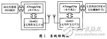
The designed wireless temperature sensor is mainly composed of the following components: temperature measurement, transmitting part, receiving part, LCD display part and control part. The system structure diagram is shown in Figure 1.
2.1 Temperature measurement circuit
The 1-Wire bus digital temperature sensor DS18B20 from Dallas is used in the temperature measurement circuit. The temperature measurement circuit is shown in Figure 2.
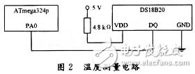
DS18B20 is a 3-pin TO-92 small package; temperature measurement range is -55 ~ 125 ° C, programmable 9-12 A / D conversion accuracy, temperature resolution up to 0.062 5 ° C, measured temperature to 16-bit digital serial output with sign extension.
The internal structure of the DS18B20 consists of four main components: a 64-bit ROM, a temperature sensor, a non-volatile temperature alarm trigger TH and TL, and a configuration register. The 64-bit serial number in the ROM is lithographed before leaving the factory. It can be regarded as the address sequence code of the DS18B20. The 64-bit serial number of each DS18B20 is different. The role of the ROM is to make each DS18B20 different, so that multiple DS181E0 can be connected to one bus.
The temperature sensor in the DS18B20 performs temperature measurement and is provided in a two's complement form with a 16-bit sign extension, expressed as 0.062 5°C/LSB. For example, the digital output of +25.062 5°C is 0191H, and the digital output of -25.062 5°C is FF6FH.
The high and low temperature alarm triggers TH and TL, the configuration registers are all composed of one byte of E2PROM, which can be written to the TH, TL or configuration registers using a memory function command. The format of the configuration register is as follows:
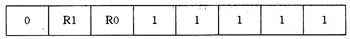
R1 and R0 determine the precision digits of temperature conversion: R1R0=“00â€, 9-bit precision, maximum conversion time is 93.75 ms; R1R0=“01â€, 10-bit precision, maximum conversion time is 187.5 ms; R1R0=“10†11-bit precision, maximum conversion time is 375 ms; R1R0; "11", 12-bit precision, maximum conversion time is 750 ms; default is 12-bit precision when not programmed. The design takes R1R0 = "11".
2.2 Wireless Transceiver Circuit
2.2.1 Interface between IA4421 and MCU
IA4421 supports SPI communication protocol. This design selects ATmega324p, a high-performance single-chip microcomputer produced by American ATMEL Company. It has built-in enhanced SPI interface and 32 kB FLASH, which can display Chinese characters on the LCD in the system. The interface circuit diagram of IA4421 and MCU is shown as in Fig. 3.
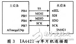
The ATmega324p's built-in enhanced serial peripheral interface SPI provides access to a full-duplex synchronous serial bus. The four signals used by the SPI are MOSI, MISO, SCK and SS. MOSI is used for serial data transfer from the master to the slave; MISO is used for serial data transfer from the device to the master; SCK is used to synchronize serial data between the master and slave on the MOSI and MISO lines transmission.
2.2.2 Wireless transmission timing
The transmission mode of IA4421 is the transmission mode of the transmission register buffer. It is enabled by the 7th el of the configuration setting command. As can be seen from Figure 1, the IA4421 has two 8-bit data registers, and the transmitted data is first latched into it. In a data register, when bit 5 of the power management command is set to 1, the transmitter begins to send data out of the first register at the set bit rate.
Each time data is sent, 0xAA must be used as the preamble of the transmitted data, otherwise the external receiving device cannot receive the data. If the synchronous mode is used, 0x2DD4 should be used as the signature of the synchronous mode before data can be transmitted. The pin nIRQ can be used to detect if the register is ready to receive the next byte from the microprocessor for transmission. If the pin nIRQ goes low, the register is ready.
2.2.3 Wireless Receive Timing
There are two ways to receive the IA4421: one is to receive all the time; the other is FIFO mode. The former method is not recommended and will cause a high bit error rate. This design uses the latter model. After the corresponding control word is set, the data has entered the buffer. If the pin nIRQ goes low, it indicates that the IA4421 is ready to receive data. At this time, the FIFO read command word is sent to start receiving.
2.3 Peripheral antenna design
The IA4421's support antenna is directly driven, and the design is quite simple and convenient, and the communication distance is long. A 50 Ω external spiral antenna and corresponding differential circuit enable data transmission and reception. The antenna designed by this system is realized by a single-core copper wire of 1.17 cm, the diameter of the wire is 0.6 mm, and the metal rod of the screwdriver is used to make 7 turns into a spiral shape. After the experiment, the actual effective communication distance can reach 200 m, which satisfies the system needs.
Double Burner Electric Hotplate
Double Iron Hotplate,Double Burner Electric Hotplate,220V Hotplate,Double Burner Hot Plate
Shaoxing Haoda Electrical Appliance Co.,Ltd , https://www.hotplates.nl