introduction
Intelligent and portable is the development trend of modern electronic products, and the intelligentization of medical electronics makes the operation of medical personnel more convenient. The medical staff can carry the handheld monitor to carry out real-time monitoring of each ward, and timely understand the relevant situation; in case of sudden situation, such as drip below the set warning value, the terminal monitoring device can generate an interrupt signal, and the main control terminal can give priority to the operation. Corresponding processing. This design realizes a portable remote wireless drip monitoring system based on AT32UC3A0512[1] single-chip microcomputer, which can timely understand the drip state and improve the safety of medical drip equipment.
1 Introduction to system principle
The system mainly includes two parts: a handheld control terminal and a terminal monitoring device. The handheld control terminal mainly implements the operation of the information input and the query interface, and inputs the ward number and the drip speed value to be queried, and sends the data to the corresponding ward monitoring terminal in the form of a data packet, and displays the drip state data information transmitted by the terminal in real time. The terminal monitoring device is mainly responsible for data collection and processing of the drip state (drip flow rate and drip level, etc.), and sends the processed data to the main control terminal through wireless communication; for the drip liquid level is lower than the set value, the patient calls Wait for an emergency, process according to the interrupt mode, issue an alarm prompt, and send the event type to the main control terminal in the form of a packet. The structural block diagram of the system is shown in Figure 1.
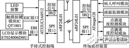
Figure 1 system block diagram
2 system hardware design
2.1 Control part hardware design
The handheld control terminal uses Atmel's 32-bit RISC processor AT32UC3A0512 as the main controller [1]. It has low power consumption and high throughput. It has 512K Flash and 64K SRAM inside. The CPU can operate up to 66 MHz. At 3.3 V, the operating current is about 40 mA and the standby current is only 30 μA. Internally highly integrated hardware resources simplify peripheral circuit design, such as internal Flash, USB, ADC, EBI, and Ethernet peripheral interfaces for designers to use.
2.1.1 Touch button module
The Quantum Research Group's capacitive touch button module IC QT1801, [2] features low power consumption, simple peripheral circuitry, and support for eight touch button inputs. After internal filtering and shaping, the logic level is output at the corresponding button port, and various modes of the IC QT1801 can be set according to different peripheral resistance values. The working mode is set as follows: In full mode (Full OpTIon Mode), connect 1 MΩ resistor on pin SNSx (x=0,1,...,7); in compact mode, it needs to be on pins SNS6K and SNS7. Connect a 1 MΩ resistor in series. There are two key output value modes: Oneperkey and Binary Code. When there is a button touch, a touch interrupt signal is generated at the 24-pin (DETECT), and the high level is valid. Among them, CS1~CS5 are touch button inputs, and the interface circuit is shown in Figure 2.
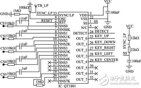
Figure 2 touch button module circuit diagram
2.1.2 LCD display module
The display part adopts EDT's LCD display module ET024006DHU. The LCD module integrates the graphic control driver HX8347A. The MCU can control the display of the LCD by reading/writing its internal registers through two interfaces, which are the parallel interface mode and SPI interface mode. 8/16-bit data and 16/18-bit RGB data can be selected in the parallel interface mode, and 8/16-bit data and 16/18-bit RGB data can be directly written to the internal registers in the serial SPI interface mode.
2.1.3 Wireless Communication Module nRF24L01[3]
The wireless communication part adopts a single-chip radio frequency transceiver chip, and its working frequency band is the universal ISM frequency band (2.4 to 2.5 GHz), which is a true GFSK single transceiver chip. Built-in link layer, with automatic response and automatic retransmission function, support address and CRC check function. It has extremely low current consumption, lower current consumption in power-down and standby mode; data transfer rate up to 2 Mbps, built-in standard SPI interface for data transfer with MCU, up to 8 Mbps; 125 optional channels, in the receiving mode, can simultaneously receive data of 6 data channels working on the same channel, and the data channels of the transceivers communicating with each other are set to the same address.
Through the read/write of the internal register of nRF24L01 to control the conversion of its working state and the transmission and reception of data, when the transceiver data receiving/transmitting is completed or an abnormality occurs, the IRQ pin generates an interrupt signal, which is active low, corresponding to the STATUS register. Bit write "1" to clear the interrupt flag. The wireless communication module hardware connection is shown in Figure 3.
2.2 Terminal monitoring device hardware design
The terminal monitoring device adopts ATmega128 single-chip microcomputer, mainly receives the command data sent by the control terminal, and sends the collected data to the control terminal to complete the functions of patient call, liquid level monitoring, detection and control of drip speed, and sound alarm.
2.2.1 Drip speed control module
The drip speed control circuit uses a dedicated stepper motor control chip L297 and a dual full bridge stepper motor drive chip L298. The PWM chopper circuit inside the L297 can generate PWM waves in the switching mode to control the current in the motor windings to control the precise rotation of the motor. The 4-phase control signal it generates can be used to control two-phase bipolar and four-phase single Polar stepper motor. The L298 contains HBridge high-voltage, high-current dual-bridge driver. The 4-channel drive circuit can drive two-phase or four-phase stepper motors up to 46 V and 2 A, which can realize the forward and reverse of the stepper motor. By precisely controlling the forward and reverse rotation of the motor to control the sliding of the flow rate clamp roller of the drip device, the purpose of controlling the drip drop speed is achieved. The hardware connection diagram is shown in Figure 4.
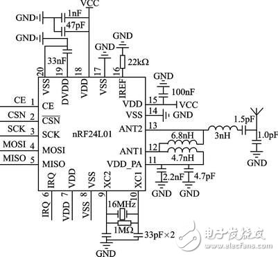
Figure 3 wireless module hardware diagram
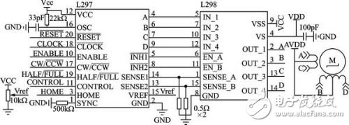
Figure 4 Drop speed control circuit diagram
2.2.2 Drip speed and level detection module
The droplet velocity was measured using an infrared tube emission method. The dot detection circuit includes infrared emission, reception, and pulse shaping. The hardware schematic is shown in Figure 5. The ST1150 is a single-speed, direct-fire infrared photoelectric sensor with a slit width of 1.5 mm, an optical axis center of 2.5 mm, and a small infrared detection area. When no droplets pass, the receiving tube (the transistor inside ST1150) is turned on, Vin is low; when there is a droplet passing, the receiving tube is cut off, a high-level pulse is generated at Vin, and the Schmitt trigger is shaped. A series of regular square wave pulses are then generated at Vout and sent to ATmega128 for processing.
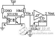
Figure 5 Drop speed detection circuit
The liquid level detection uses a reflective infrared sensor, and the circuit detection principle circuit is similar to the drip speed detection circuit. The ST198 is a reflective photoelectric sensor consisting of a high-transmittance infrared photodiode and a high-sensitivity phototransistor. It is non-contact detection and is available when the detection distance is 2 to 10 mm. When the liquid level is lower than the set value, the receiving tube receives the level signal, which is inverted by the inverter and sent to the MCU to trigger the interrupt. When the infrared tube is ST1150, it is used for droplet velocity detection, and when it is ST198, it is used for liquid level detection.
3 system software structure
(1) Data frame structure
A communication data frame structure is defined to manage communication between the control terminal and the device. By parsing the data frame, the master/slave device can perform data processing with high efficiency. According to the order of communication transmission, the format of the data frame is: command (1 byte) + device ID (1 byte) + event type (1 byte) + data field length (1 byte) + data field (n word) Section) + checksum (2 bytes).
(2) Migration of μC/OSII
μC/OSII is an open source, structure-cuttable RTOS that can deprive real-time kernels. Most of the code is C language, which is highly portable and has been ported on multiple CPUs. AVR Studio 5 integrates the Software Framework package, including the Atmel MCU interface driver function. In the AVR Studio 5 environment, porting μC/OSII to the AT32UC3A0512 MCU requires the following modifications in the Micrium official migration instance:
1 Modify the contents of the excepTIon.S file and modify it as follows:
_handle_Supervisor_Call:
Lddpcpc, __OSCtxSw
__OSCtxSw:.
longOSCtxSw
2 Modify the contents of cpu.h as follows:
#define CPU_CRITICAL_ENTER()
{cpu_sr = CPU_SR_Save();}
#define CPU_CRITICAL_EXIT()
{CPU_SR_Restore(cpu_sr);}
#define CPU_SR_Save()cpu_irq_save()
#define CPU_SR_Restore(cpu_sr)
Cpu_irq_restore(cpu_sr)
#define CPU_IntDis()Enable_global_interrupt()
#define CPU_IntEn()Disable_global_interrupt()
#define CPU_ExceptDis()Disable_global_exception()
#define CPU_ExceptEn()Enable_global_exception()
#define CPU_Reset()Reset_CPU()
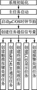
Figure 6 Software structure diagram of the main control terminal
(3) Controller part software design
The software structure under the μC/OSII system is shown in Figure 6.
The main control terminal mainly completes the user's operation through the LCD interface. The five touch keys are interface operation buttons, and the numeric keypad is realized by software. Enter the ward number to be queried through the numeric keypad. After confirming, you can check the speed and margin of the ward.
The switching relationship of the interface menu is realized by defining a structure, which is defined as:
Typedef struct MenuItem{
U8 MenuNum; / / when the number of layer menu items
U8 *DispStr; / / display string
Struct MenuItem *ChildrenMenus;//submenu node
Struct MenuItem *ParentMenus; // parent menu node
} Menu;
(4) Software design of terminal monitoring part
The terminal receives the command data packet sent by the control terminal, parses the command, performs corresponding processing, and packages the data and sends it to the control terminal. The software flow of the terminal control part is shown in Figure 7.
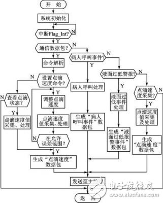
Figure 7 terminal main program
Conclusion
Based on the embedded system of AVR32MCU and μC/OSII, remote online monitoring is realized by wireless communication, and the establishment of wireless network enhances the mobility of the system. The design of a portable drip monitoring system based on AVR32 proposed in this paper will miniaturize the medical drip monitoring device and stabilize the system in a short range. Due to limited resources, network formation for remote control is still being explored.
Plastic Coated Electric Kettle
The original stainless steel double wall Electric Kettle. This kettle comes with 100% stainless steel interior. Outside made by plastic for protect your hand in case that the hot stainless steel will scald your hand. No plastic in contact with hot water. The spacious kettle has a volume of 1.8 liters which give ample space to boil tea, coffee or soups in minutes. Lets you boil a huge quantity of liquid at a time and helps save time and electricity.
· Stainless Steel Body With Plastic Outside: Ergonomic in design, the electric kettle has a sturdy handle with smart contours to make your grip a firmer one. The stainless steel finish gives a glossy feel and boasts a rust-free performance. This stainless electric kettle comes with a convenient spout so that liquid can be easily poured from it directly into a container. It avoids any spillage and thus prevents your kitchen from getting messy.
· 360 degree rotational body with separated base: Enjoy the ease and convenience of cord-free serving with this stylish stainless steel kettle. Perfect for placing on the table for gatherings or leaving on the base for worry-free hot water any time of day.
· Automatic shut off when water boils or dry: This overheat safety protection feature of the electric Kettle helps to prevent hazardous accidents. The cordless electric kettle switches off if the water inside the kettle dries up. It also saves on electricity as it uses very less power.
· Lightweight and Portable: Carry your kettle anywhere to enjoy a warm cup of coffee or tea away from your home. Kettle not only looks good but maintains a high standard in terms of durability. Lightweight and its small dimensions snugly fit in your bag. Portable and small in size, this electric kettle makes a perfect travel companion.
· Cool touch Exterior: With out cool-touch design. You`ll be able to touch the outside of the kettle even when it`s boiling. There`s no risk of getting accidentally burnt, so it`s perfect for homes with young children.
Application:
Enjoy your coffee.
Cook egg for morning.
Boil some lemon tea
Plastic Coated Electric Kettle
Plastic Coated Electric Kettle,Household Plastic Kettle,Colorful Water Kettle,Auto Shut-Off Electric Kettle
Guangzhou Taipeng Electrical Appliances Technology CO., LTD. , https://www.kettles.pl