The two-wire smart meter is widely used in primary instruments for process parameter detection such as pressure and temperature because of its simple application and low cost. However, the two-wire loop requires simultaneous transmission of energy and high-precision signals, which makes signal isolation very difficult. This article describes the basic workings of a two-wire loop. Based on this, the deficiencies of the existing passive current signal isolators in the two-wire signal isolation circuit are analyzed. The signal isolation scheme based on TS107L-F-2 two-wire isolated converter with higher transmission accuracy is introduced. And its power distribution expansion plan. Finally, the Hart signal isolation transmission scheme of the TS107HL-F-2 in the two-wire loop is introduced for the communication requirements of the smart meter.
The basic way of two-wire signal transmission
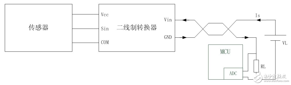
Figure 1 Two-wire system typical application block diagram
A typical circuit for a two-wire signal transmission method is shown in Figure 1. The signal detection terminal mainly comprises a sensor and a two-wire converter. The signal receiving end comprises a two-wire loop power supply VL and a current detecting circuit. The general current detecting circuit converts the current signal into a voltage signal by the precision resistor RL and transmits it to the control system through AD conversion.
The function of the two-wire converter is to convert the voltage Vin of the two-wire loop into the supply voltage Vcc of the sensor, and control the load current Is of the two-wire loop Vin according to the input signal Sin of the sensor. Here Is is the 4~20mA current signal transmitted by the two-wire system.
In the two-wire loop, there is only one voltage source VL, and the loads are Vin and VRL, respectively. Since the current detecting resistor flows through the current signal Is, the voltage VRL is determined by Is without the resistance being constant. According to Kirchhoff's voltage law, the voltage Vin of the two-wire interface should change with the change of VRL and satisfy the following equation (1):
Vin=VL-VRL (regardless of the voltage drop of the line impedance) (1)
Since Is is determined by the circuit signal, Vin determines the input energy of the two-wire converter, which in turn determines the maximum output energy of the two-wire converter Vcc.
Conventional isolation scheme for two-wire applications
In an instrument field process signal detection application, the signal detection terminal and the signal collection terminal need to transmit signals through a long signal transmission line. Since the primary instrument is mostly a metal casing, it needs to be grounded during use, so the signal transmission line is also connected to the earth through the two-wire interface. At this time, the signal transmission line is like a grounding antenna, which can effectively receive various electromagnetic wave signals. At the same time, all kinds of charges accumulated to the transmission line will be introduced into the earth through the two-wire interface, which will greatly interfere with the signal transmission of the two-wire system.
In order to suppress the interference of the signal transmission line grounding to the signal, in practical applications, it is generally required to isolate the signal transmission line before it is connected to the sensor. The conventional solution is shown in Figure 2. A passive current signal isolator is added between the two-wire loop and the two-wire converter to achieve isolated signal transmission. The passive current signal isolator used in the figure is the T1100L-F of Jin Shengyang.
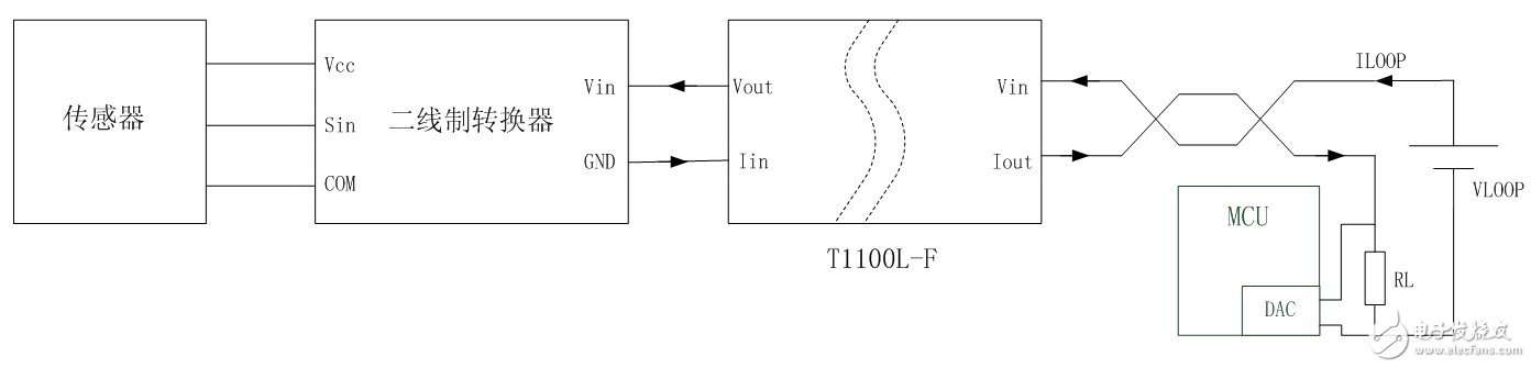
Figure 2 Existing two-wire loop isolation scheme
The T1100L-F can transmit 4~20mA current signals in isolation without external power supply. When the input voltage of the energy reaches up to 30V, the output can realize the output of the highest voltage of 25V and the signal current, effectively achieving the isolated transmission of signals and energy. The scheme is simple to use and is suitable for various occasions requiring 4~20mA current signal isolation, but there are still deficiencies, including the following two points:
1. Low signal transmission accuracy
Passive signal isolators typically have a signal transmission accuracy of less than 0.3% due to the simultaneous isolation of the transmitted current and energy.
This article is selected from the Electronic Consumers Network June "Smart Industry Special" Change The World column, please indicate the source!
  
Magicard Printers Cleaning Kits
Magicard Cleaning Kit,Magicard Enduro Cleaning Kit,Magicard Rio Pro Cleaning Kit,Magicard Rio Pro Cleaning
Miraclean Technology Co., Ltd. , https://www.mrccleanroom.com